Troubleshooting Blown Components on Exercise Equipment Control Boards
Motor Control Board Repair: Start With the Cause
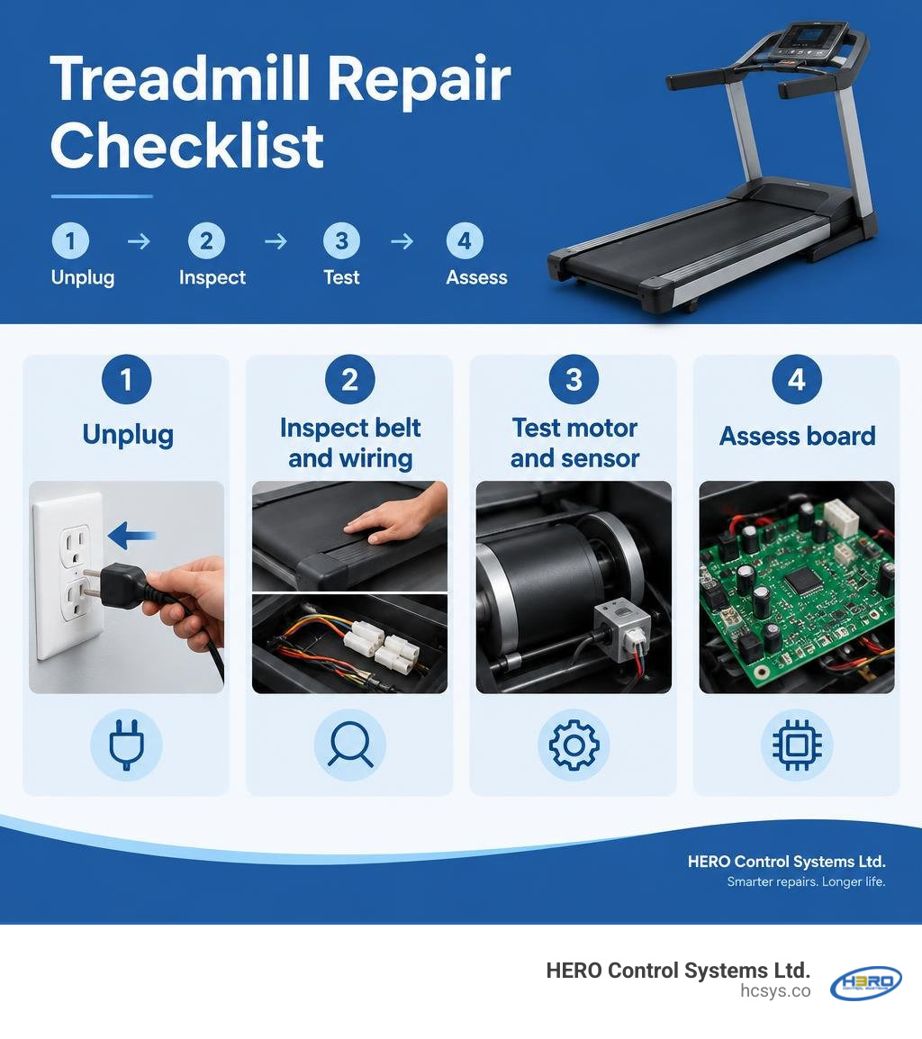
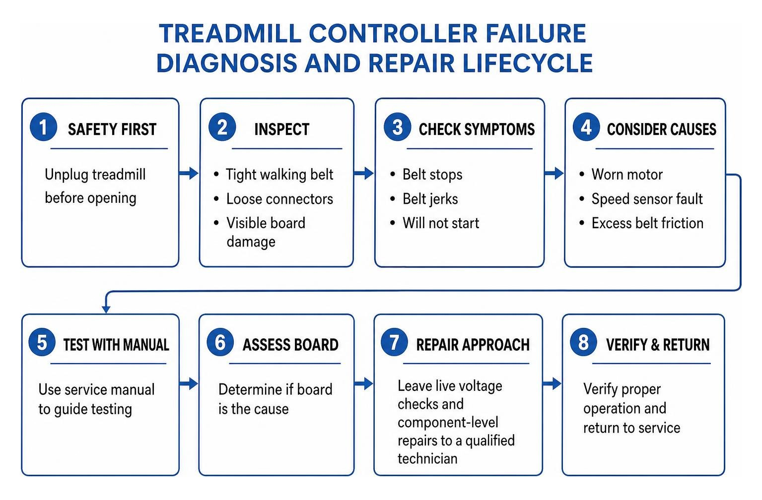
For motor control board repair, unplug the treadmill before opening it. Check for a tight walking belt, loose connectors, and visible board damage. If the belt stops, jerks, or will not start, do not assume the board is faulty: a worn motor, speed sensor fault, or excess belt friction can cause similar symptoms. Use the service manual to guide testing. Leave live voltage checks and component-level repairs to a qualified technician.
The motor control board regulates power to the drive motor, so finding the cause matters before replacing parts. I’m Eng. Cephas Kalembo, founder and CTO of HERO Control Systems Ltd. in Lusaka. My experience in PCB design and industrial electronics repair informs this approach to motor control board repair.
For related board-level repair guidance, see these practical circuit board fix methods, a diagnostic reference, and a repair troubleshooting guide.
Common Symptoms and Root Causes of Exercise Equipment Controller Failure
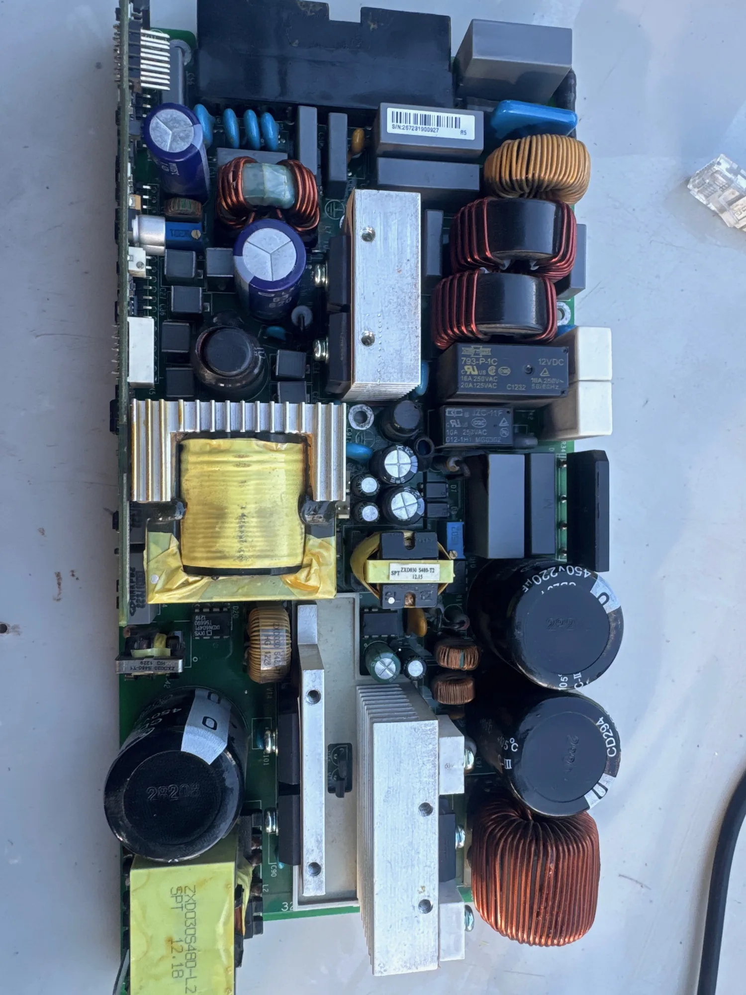
When an exercise machine abruptly quits mid-workout, the lower motor control board (MCB) is often the first suspect. The MCB acts as the intermediate brain and power muscle: it takes low-voltage Pulse-Width Modulation (PWM) signals from the upper console and chops incoming rectified AC power into a regulated direct current (DC) supply—typically ranging from 40 to 120 volts DC—to drive the treadmill's heavy motor.
When things go wrong, the failure usually presents through distinctive symptoms:
- Sudden Belt Stoppage: The machine powers on, displays a countdown, starts for two seconds, and abruptly cuts out as internal overcurrent protection trips.
- Tripped Circuit Breakers: Flipping the treadmill's master switch immediately trips your home or gym breaker, indicating a dead short across the input bridge rectifier or power transistors.
- Motor Stuttering or Jerking: The walking deck shudders or moves erratically at low speeds, pointing to broken switching pulses or failing filtering stages.
- Acrid Burning Odor: Burnt silicon or vaporized epoxy resin leaves an unmistakable smell. If your machine smells like scorched toast, internal semiconductor switching elements have likely met a dramatic end.
Root causes rarely begin on the printed circuit board itself. More often, neglected mechanical maintenance drives electrical failure. As walking belts lose lubrication, dynamic friction between the belt and deck climbs steeply. This forces the DC motor to draw continuous high amperage, overloading the switching MOSFETs or IGBTs. The resulting thermal stress breaks down the thermal paste coupling the components to the aluminum heat sink, leading to thermal runaway and complete semiconductor breakdown.
Interpreting LED Diagnostic Signals and Console Error Codes
Modern motor control boards feature onboard diagnostic LEDs to communicate hardware state without needing an immediate oscilloscope hookup.
- Solid Red Status LED: On industry-standard controllers like the MC-2100 series, a solid red LED during a sudden belt stall usually indicates an active overcurrent protection lock or loss of tachometer feedback.
- Slow Blinking Diagnostic LED: A steady pulse typically signifies normal standby operation, showing the microcontroller is healthy and awaiting a speed command from the upper console.
- Rapid Flashing or Dark LED: A rapidly blinking LED often points to incoming voltage anomalies (undervoltage or overvoltage on the DC bus). A completely dark LED when mains power is active indicates a blown onboard fuse or a dead low-voltage auxiliary power supply stage.
Console error codes provide additional clues. Codes like E01 or E02 commonly denote speed sensor feedback timeouts, whereas E05, E06, or F11 often signal drive board communication loss or high-amperage overcurrent events.
Differentiating Controller Faults from Motor and Speed Sensor Issues
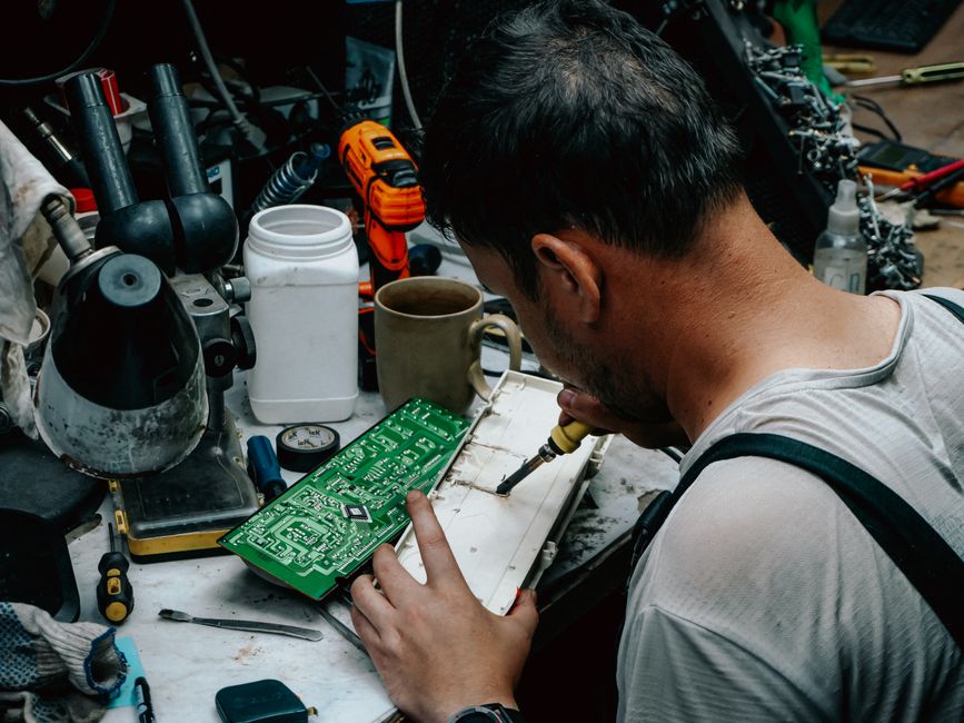
Before unsoldering components, you must isolate the failure to ensure you aren't blaming a healthy board for a dead motor or faulty sensor. We follow standard motor inspection procedures to test the drive mechanism systematically:
- Check Motor Windings: Disconnect the heavy red (A+) and black (A-) motor leads from the controller. Set your digital multimeter to ohms (resistance). A healthy treadmill DC drive motor typically displays a winding resistance between 1.0 and 4.0 ohms across its terminals. If the meter shows 0 ohms (a dead short) or infinite resistance (an open circuit), the motor windings are burned out or the carbon brushes are completely worn down.
- Inspect the Optical/Hall Speed Sensor: Treadmills utilize either a magnetic reed switch or an optical tachometer wheel on the front roller pulley. Rotate the drive roller slowly by hand. With your multimeter set to DC voltage across the sensor signal leads, verify that the signal cleanly toggles between 0V and 5V. If the signal remains pinned at one voltage level, the console cannot detect belt movement and will shut the motor controller down within two seconds as a safety precaution.
- Evaluate Mechanical Drag: With the treadmill completely unplugged, push the walking belt manually. It should glide with smooth, moderate resistance. If pushing requires substantial physical effort, the deck needs cleaning and specialized silicone lubrication before any newly repaired board is installed.
Step-by-Step Motor Control Board Repair for Treadmills and Gym Gear
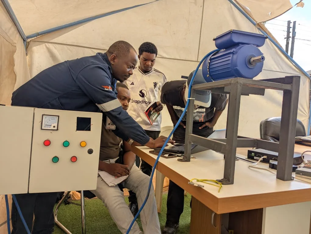
Refurbishing a damaged motor controller demands a methodical, safety-first workflow. High-power exercise equipment controllers store hazardous electrical energy long after the wall plug is pulled.
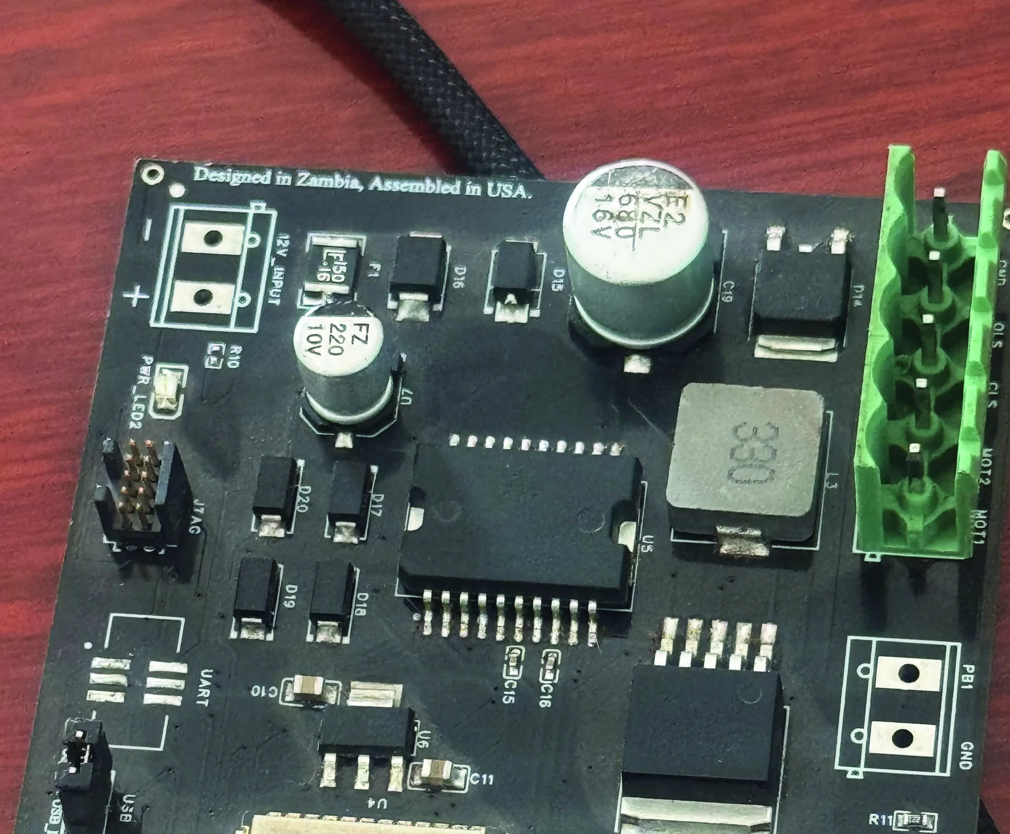
Warning: Discharge Capacitors First! High-voltage electrolytic filter capacitors retain direct current charges exceeding 160V DC. Before touching any trace or component lead, place a 500-ohm, 5-watt ceramic power resistor across the large capacitor terminals for 30 to 45 seconds to safely bleed off stored energy. Never short capacitor terminals directly with a metal screwdriver, as this causes violent arcing, damages component pads, and risks personal injury. Check with a multimeter to verify 0.0V across the bus before proceeding, adopting proven practical circuit board fix methods.
Essential Diagnostic Tools for Motor Control Board Repair
To accurately evaluate and repair these boards, assemble the following tools:
- Digital Multimeter (DMM): Equipped with fast continuity, diode test, DC millivolts, and capacitance modes.
- Temperature-Controlled Soldering Station: A 60W to 100W iron is necessary to quickly transfer heat to heavy copper planes and thick heat-sink ground joints.
- Desoldering Pump or Solder Wick: Essential for clearing heavy through-hole component leads without lifting fragile copper eyelets.
- High-Quality Consumables: Leaded or lead-free rosin-core solder, no-clean liquid flux pen, non-conductive electronic-grade RTV silicone, and premium zinc-oxide or ceramic-based thermal paste.
Testing Output Voltages, Diodes, and Blown Power MOSFETs
With the controller safely on the bench, run through these primary electrical checkpoints, keeping powertrain inverter and drive troubleshooting guidelines in mind:
- Bridge Rectifier Inspection: Set your multimeter to Diode Check mode. Place the negative probe on the DC positive terminal of the rectifier and probe each AC input pin with the positive lead; you should observe a typical silicon forward voltage drop between 0.4V and 0.7V. Reverse the probes to ensure the meter shows an open circuit (OL). Any reading near 0.00V indicates a shorted internal diode that will blow mains fuses instantly.
- Power MOSFET / IGBT Junction Test: Locate the power switching transistors mounted against the main aluminum heat sink (common types include G40N60, IRFP250, or IRFP260). Probe between the Drain and Source (or Collector and Emitter). A healthy switch shows a standard diode reading across the internal body diode and an open circuit when reversed. If you measure continuity or near-zero resistance between the Gate and Drain, the gate insulation has ruptured, sending destructive high voltage into the low-voltage driving logic.
- Live Output Voltage Verification (Qualified Technicians Only): If the board powers up safely on a test jig, measure the DC output voltage across the motor terminals while supplying a run command. A functional board will scale voltage smoothly upward from 10V DC to over 90V DC as target speed increases. If the voltage collapses below 10V DC under a minimal test load, the pulse-width modulation output driver is compromised.
Replacing Damaged Capacitors, Gate Drivers, and Lifted PCB Traces
When desoldering high-power components, old single-sided and double-sided boards can easily suffer damage.
- Replacing Filter Capacitors: Swollen tops or crusty electrolyte deposits around the base indicate dead electrolytic filter capacitors. Always replace them with high-temperature (rated for 105 degrees Celsius), low-ESR (Equivalent Series Resistance) capacitors matching the original voltage rating or higher.
- Replacing Optocouplers and Gate Drivers: Whenever a power MOSFET suffers a short-circuit blowout, replace the associated optocoupler (such as an MOC3052 or 4N35) and gate resistors. A shorted high-voltage transistor almost always sends back-EMF spikes into the driving gate circuit.
- Remediating Lifted Traces and Pad Delamination: High current surges can vaporize narrow copper traces right off the fiberglass substrate. When repairing trace breaks, jump the gap using insulated copper wire anchored with epoxy, using proven methods for repairing lifted solder pads and traces.
- Thermal Interface Reinstallation: Thoroughly clean old, dried thermal compound off the heat sink using 99% isopropyl alcohol. Apply a thin, even layer of fresh thermal compound before tightening mounting screws. Never apply thick blobs; excessive paste acts as a thermal insulator rather than a conductor, causing premature semiconductor overheating.
Evaluating Replacement Parts and Repair Options
When an exercise machine's control board fails, you have three primary paths forward: perform component-level circuit repair, purchase a factory-original replacement unit, or commission an engineered custom replacement board.
| Option | Typical Cost Range | Turnaround Time | Best Suited For | Key Advantages |
|---|---|---|---|---|
| DIY Component Repair | $15 – $45 (Parts) | 1 – 3 Days | Enthusiasts with soldering skills | Lowest raw material expense; quick turnaround |
| Professional Refurbishment | $140 – $180 | 3 – 7 Days | Standard consumer fitness equipment | Root-cause analysis, load bench testing, and warranties |
| OEM Direct Replacement | $120 – $320+ | 3 – 10 Days | Readily available active brand models | Drop-in factory matching harness compatibility |
| Custom Engineered Board | Variable / Project-based | Engineered to order | Obsolete, industrial, or unfindable legacy boards | Modern component architecture; eliminates future obsolescence |
Common consumer exercise equipment motor controllers include the MC-60, MC-2100 series, and model-specific controllers for brands like Sole, NordicTrack, and ProForm. When identifying replacement units, always read the exact part number stamped on the PCB barcode label rather than relying solely on the treadmill's external model name.
Cost Analysis: New Replacement vs. Motor Control Board Repair
Navigating the economics of hardware repair comes down to a straightforward engineering rule of thumb: the 50-percent repair rule. If repairing the board costs less than half the price of a brand-new, guaranteed replacement assembly, refurbishment is the clear, sustainable choice.
For example, a new Sole controller (Part D020054) commonly retails near $296.99, while professional board repair services run around $159.99—delivering roughly 45% savings. Similarly, sourcing individual high-grade replacement MOSFETs, diodes, and capacitors costs under $30.
For older commercial gym units where OEM parts are completely discontinued, relying on custom replacement circuit board solutions provides an effective way to keep valuable machinery in service without paying for complete equipment replacements.
Frequently Asked Questions About Treadmill Control Board Troubleshooting
How do I know if my treadmill issue is the motor or the control board?
You can verify a permanent-magnet DC treadmill motor independently using a standard 12V automotive battery or a 12V DC benchtop power supply. Disconnect the motor's red and black wires from the control board and connect them directly to the 12V DC power source.
If the motor spins smoothly, quietly, and continuously at low speed, the motor windings and brush gear are healthy, meaning the failure lies in the controller's switching circuitry, power supply stage, or incoming PWM signal path.
What safety precautions are necessary before servicing a motor control board?
Always unplug the equipment from the AC wall outlet before removing protective covers. After removing power, connect a 500-ohm, 5-watt resistor across the high-voltage electrolytic filter capacitors for at least 30 seconds to bleed down stored energy.
Wear eye protection, use insulated hand tools, set up an anti-static ESD-grounded mat, and verify 0.0V DC across the board with a calibrated multimeter before touching any conductive traces or pins.
Why do power MOSFETs blow repeatedly on exercise equipment control boards?
Power transistors blow repeatedly when the underlying physical cause is left unaddressed. In treadmills, 90% of repeat semiconductor failures stem directly from a dry, worn walking belt creating excessive mechanical drag.
This high friction forces the motor to operate at continuous maximum current limits, overheating the switching transistors until thermal breakdown occurs. Always clean the deck, apply pure 100% silicone lubricant beneath the belt, and check brush alignment before installing freshly repaired control boards.
Conclusion
Tackling a failed motor controller doesn't have to mean scrapping an entire machine. By methodically diagnosing symptoms, testing power semiconductors, discharging high-voltage capacitors safely, and resolving physical friction, you can restore damaged exercise hardware reliably.
At HERO Control Systems, our engineering laboratory in Lusaka designs, manufactures, and repairs complex electronics—from industrial drives and automation hardware to custom PCB solutions. When legacy circuit boards burn out or original replacement units become impossible to source, explore our expert custom PCB design and repair services to get your critical systems running again.