Simple Fixes for Heat Pump and Furnace Control Board Failures
How to Start HVAC Control Board Repair
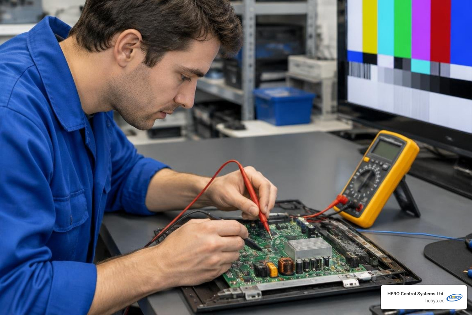
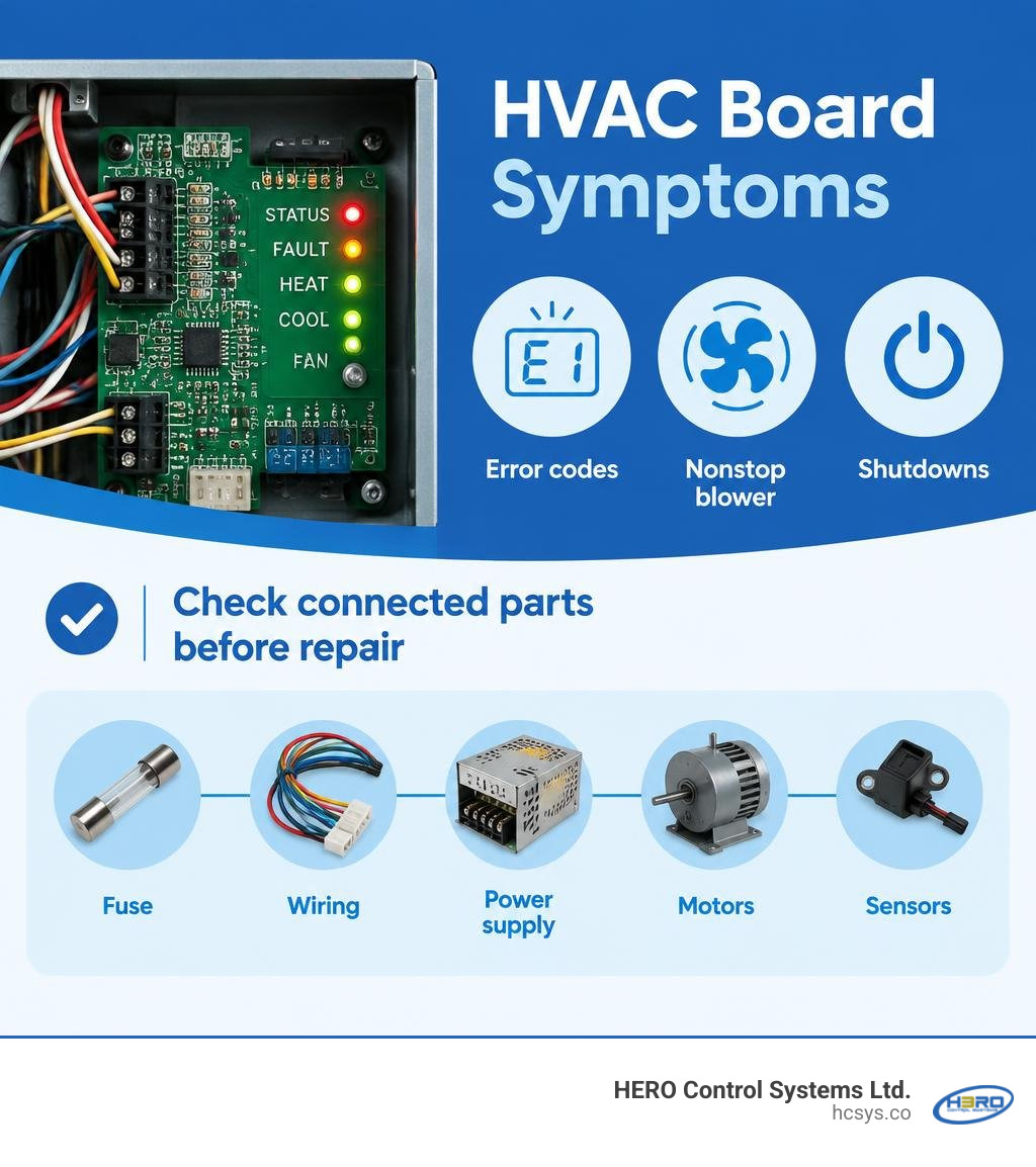
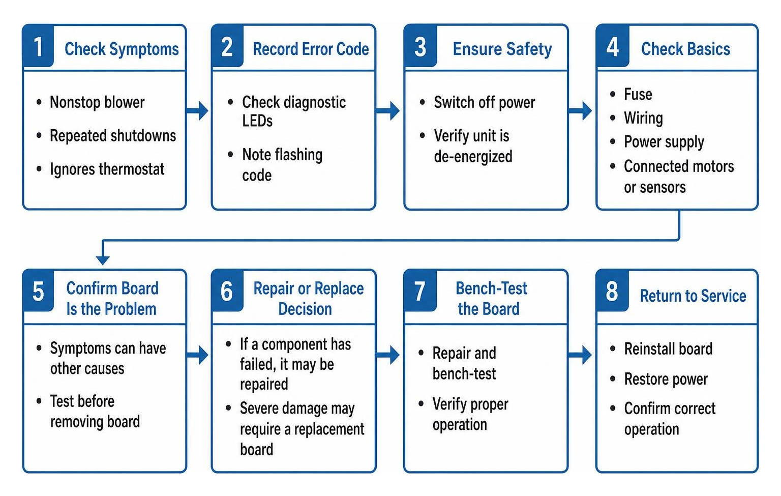
A reliable hvac control board repair starts with confirming the board is the problem. Record any flashing error code before switching off power. Then have a qualified technician verify the unit is de-energized and check the fuse, wiring, power supply, and connected motors or sensors. If a board component has failed, it may be repaired and bench-tested. Severe damage may call for a replacement board.
A blower that runs nonstop, repeated shutdowns, or a unit that ignores the thermostat can point to a board fault. But each symptom can also have another cause, so testing matters before removing the board.
I'm Eng. Cephas Kalembo, founder and CTO of HERO Control Systems Ltd. My work in PCB design and industrial electronics repair informs this guide to hvac control board repair.
Handy hvac control board repair terms:
Primary Signs and Root Causes of HVAC Control Board Failure
The control board acts as the central brain of any furnace, heat pump, or air conditioning system. It takes low-voltage signals from your thermostat, verifies that safety interlocks and limit switches are closed, and activates line-voltage loads like the inducer draft motor, hot surface igniter, gas valve, compressor, and indoor blower fan. When something goes wrong with this microprocessing hub, the whole system behaves erratically.
Understanding how to address these malfunctions begins with troubleshooting modern HVAC control board faults at the system level. A failing board commonly manifests in a few distinct behavioral patterns:
- Continuous Blower Fan Operation: If the indoor fan runs indefinitely even when the thermostat is set to "Off" or when there is no active heating or cooling call, an onboard mechanical relay has likely welded its internal contacts shut due to electrical arcing.
- Unresponsive Thermostat Calls: The thermostat clicks, sends a 24-volt alternating current (VAC) call on the yellow (cooling) or white (heating) wire, but the board fails to energize the corresponding relays.
- Intermittent Cycling and Random Lockouts: The system starts ignition, runs for several seconds or minutes, and abruptly shuts down without triggering a standard high-limit or rollout safety trip.
- Visible Diagnostic Indicators: Most modern boards feature one or more diagnostic light-emitting diodes (LEDs) that pulse specific flash sequences to communicate system status and detected faults.
Identifying Error Codes and Blower Faults
Before cutting power to a malfunctioning unit, look through the sight glass on the blower access panel to note the LED flash code. Control boards use steady flashes, rapid pulses, or two-digit heartbeat patterns to indicate whether the problem is an external sensor fault or an internal board issue.
In split systems and inverter-driven mini-splits, communication errors between the indoor air handler and outdoor condensing unit frequently point back to the control electronics. For instance, diagnosing an E1 / EL 01 / 88 Error: Communication Error - Senville requires checking the direct-current (DC) communication loop between terminals. Under normal operation, the signal line fluctuates dynamically between positive 25 volts DC and negative 25 volts DC. If the reading stays pinned at a constant DC voltage or reads strictly positive, one of the communication optocouplers or microcontrollers on the indoor or outdoor printed circuit board (PCB) has failed.
Similarly, an indoor blower fault, such as an E3 / EH 03 Error: Indoor Fan Speed Fault - Senville, can occur when the board is not providing the correct drive voltage or when its feedback circuit stops sensing motor pulses. Checking the winding resistance across the fan motor terminals confirms whether the motor has seized or if the board's switching circuitry is no longer sending power.
Environmental and Electrical Stress Factors
Control boards rarely fail without an external catalyst. Although high-grade industrial electronics are built to withstand rigorous operation, residential and light commercial HVAC equipment exposes PCBs to severe environmental stresses:
- Power Surges and Grid Spikes: Lightning strikes, utility transformer switching, and inductive voltage spikes from failing compressor contactors send high-voltage transients across the line. These spikes overwhelm onboard metal oxide varistors (MOVs) and destroy power regulation chips.
- Moisture Intrusion and Condensation: High-humidity environments, blocked condensate drain pans, and melting evaporator frost introduce moisture directly to the circuit traces. This leads to dendritic growth, short circuits, and galvanic corrosion.
- Thermal Cycling and Vibration: HVAC systems produce substantial mechanical vibration and thermal swings. Over 5 to 10 years, these forces cause solder joints to crack (cold solder joints), particularly around high-current pins on relays, terminal blocks, and power resistors.
- Dust and Pest Contamination: A buildup of conductive dust or insects crawling across high-voltage traces creates carbon bridges, leading to localized electrical arcing that chars the fiberglass substrate.
Step-by-Step Diagnostic and HVAC Control Board Repair Procedures
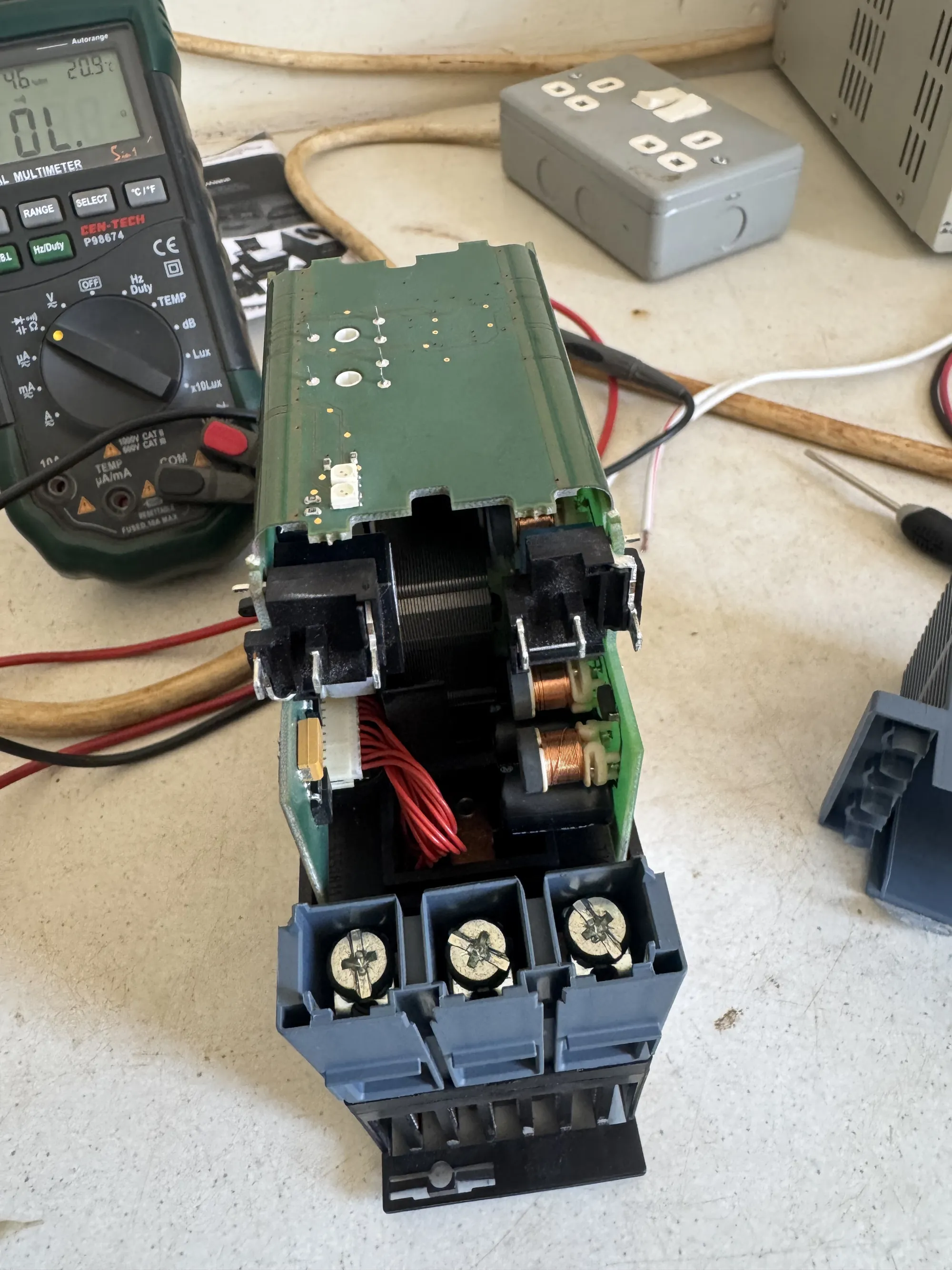
Accurate diagnosis requires systematically isolating the control board from connected peripheral loads before attempting any board-level rework.
Essential Safety Protocols for HVAC Control Board Repair
HVAC equipment operates using dangerous electrical potentials, combining 120 VAC or 240 VAC line voltage with high-energy direct-current buses on modern inverter units. Always follow rigorous safety standards before servicing:
- Disconnect All Power Sources: Switch off the dedicated circuit breaker at the main distribution panel and turn off the local service disconnect switch mounted near the equipment.
- Verify Zero Energy State: Use a calibrated digital multimeter set to alternating-current voltage (VAC) to verify zero potential across the line terminals (L1, L2/N) and earth ground.
- Discharge High-Voltage DC Capacitors: Modern inverter-driven heat pumps and variable-speed systems contain large electrolytic capacitor banks on the DC bus that store lethal direct-current charges long after mains power is severed. Adhere strictly to the safety procedures outlined in technical documentation such as A10-2004.pmd. Connect a high-wattage ceramic resistor across the DC bus terminals and monitor with a meter until the voltage safely drops to zero volts DC. Wait at least 10 minutes if test points are physically inaccessible.
- Wear Appropriate Personal Protective Equipment (PPE): Wear safety glasses and electrical-insulating gloves rated for the equipment's maximum operating voltage.
Testing Voltages and On-Board Components
Once safety protocols are established, follow this logical testing sequence:
- Check the Low-Voltage Blade Fuse: Most furnace control boards include a 3-amp or 5-amp automotive blade fuse (typically violet or amber) protecting the secondary winding of the 24 VAC step-down transformer. Remove the fuse and test it for continuity using your meter's resistance setting. A blown fuse indicates an external short circuit in the low-voltage thermostat wiring or contactor coil rather than a failed board.
- Verify Transformer Input and Output: With power temporarily restored and the door interlock switch safely engaged, verify 120 VAC across the primary transformer leads and 24 to 28 VAC across the low-voltage secondary terminals (R and C).
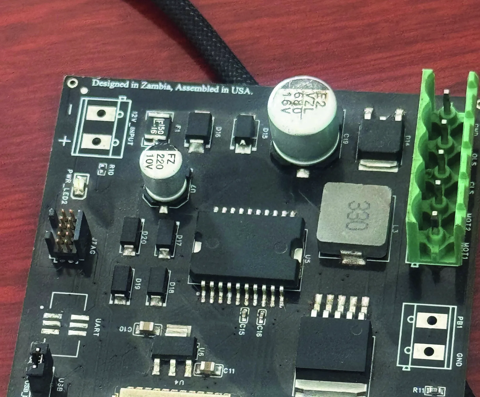
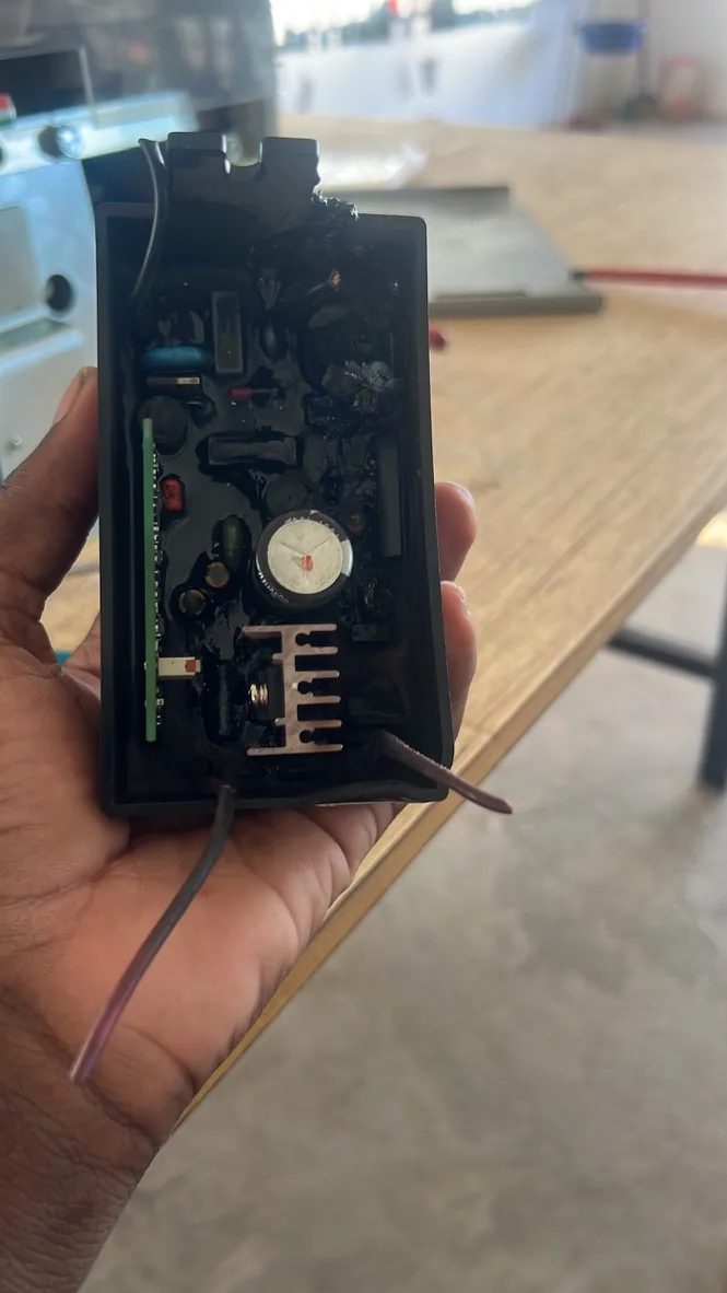
- Inspect Solder Joints and Traces: Remove the board from its plastic standoffs and inspect the reverse side under bright light. Look for ring-shaped fractures around relay pins, discolored solder pads, or traces that have vaporized due to overcurrent.
- Test Mechanical Relays: De-energize the unit, isolate the relay pins, and apply an external 12 VDC or 24 VDC bench power supply to the relay coil. Listen for a sharp mechanical click and verify near-zero resistance across the normally open (NO) contacts using your multimeter. Contacts showing high or infinite resistance have suffered internal pitting and must be replaced.
Repair vs. Replacement: Evaluating Whether Board-Level Repair Is Viable
When facing a damaged HVAC board, you must choose between repairing the existing board, sourcing a direct original equipment manufacturer (OEM) replacement, or installing a universal aftermarket board.
Repairing an existing board can save between 30% and 70% compared to purchasing a factory-new assembly. For vintage or obsolete commercial systems where manufacturers have discontinued spare parts, repairing the original board prevents full equipment replacement, which can otherwise cost tens of thousands of dollars.
| Factor | Component-Level Board Repair | OEM Board Replacement | Universal Replacement Kit |
|---|---|---|---|
| Typical Cost | Lower ($100–$250 part rework) | Moderate to High ($200–$600 part) | Moderate ($150–$350 part) |
| Compatibility | 100% exact mechanical & pin fit | 100% exact factory fit | Requires DIP switch / harness setup |
| Availability | Dependent on repair turnaround | Subject to manufacturer stock | Broadly available off-the-shelf |
| Obsolete Systems | Best solution for discontinued units | Often unavailable or obsolete | May not support specialized functions |
| DIY Feasibility | Advanced electronics soldering | Direct plug-and-play | Requires careful wiring mapping |
Checking Replacement Compatibility

When selecting a replacement, consult resources like How to Find the Right HVAC Control Board to verify critical specifications:
- Ignition Voltage and System Type: Standard furnaces utilize either 80 VAC or 120 VAC hot surface igniters (HSI) or direct spark ignition (DSI). Installing a board with mismatched ignition parameters will damage the igniter.
- Blower Motor Drive Architecture: Verify whether your system uses multi-speed permanent split capacitor (PSC) taps or electronically commutated motors (ECM) driven by pulse-width modulation (PWM) or serial communication.
- Accessory Relays: Ensure the board has dedicated terminal outputs for electronic air cleaners (EAC) and humidifiers (HUM) if your setup utilizes them.
- DIP Switch and Jumper Configurations: Universal boards use configurable DIP switches to set pre-purge timings, heat-off delay intervals, and fan speeds. Always replicate the exact switch positions from the original unit.
When replacing boards on complex mini-split systems, ensure you follow manufacturer-specific guidelines such as the Proper Board Replacement for GREE Mini. These systems require cleaning mating surfaces, applying fresh thermal paste to onboard intelligent power modules (IPMs), and following proper screw torque sequences to prevent thermal breakdown.
Professional HVAC Control Board Repair and Bench Testing
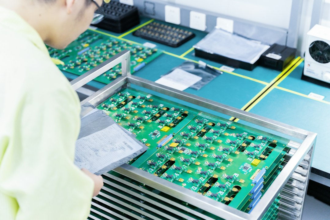
For complex issues involving surface-mount microcontrollers, flash memory corruption, or extensive trace damage, professional board-level repair is the most reliable route. Specialized industrial electronic repair facilities de-solder failed components using temperature-controlled rework stations, install industrial-grade replacements, and run comprehensive bench tests.
Professional repair services validate the entire input/output chain under simulated operating loads—cycling relays, checking flame rectification circuits, and verifying DC bus stability—often backing their work with 1- to 2-year service warranties that exceed standard OEM electronics coverage.
Frequently Asked Questions About HVAC Control Board Repair
How much does it cost to repair or replace an HVAC control board?
DIY replacement parts range from $100 to $600 depending on whether you purchase a universal kit or a brand-specific OEM controller. Professional installation by a licensed HVAC contractor typically ranges from $550 to $1,300, which includes diagnostic labor, safety testing, and warranty coverage. Dedicated component-level board repair services generally charge between $150 and $250, saving 30% to 70% compared to new control assemblies.
What is the expected lifespan of a heat pump or furnace control board?
Under ideal operating conditions, a quality HVAC control board is engineered to last 15 to 20 years. However, power surges, dust accumulation, excessive vibration, and moisture frequently cause boards to fail within 5 to 10 years. Installing whole-house surge protection, replacing air filters regularly, and keeping electrical cabinets clean can extend the operational life of the electronics.
When should a control board be repaired or replaced?
A board is an ideal candidate for component repair if the damage is localized to discrete, replaceable parts like electromechanical relays, electrolytic capacitors, blown varistors, or cold solder joints. If the PCB substrate is deeply charred, multi-layer traces have delaminated, or a proprietary microcontroller with unobtainable firmware has burned out, replacing the board entirely with an OEM or universal unit is the safer, more cost-effective choice.
Conclusion
A malfunctioning HVAC control board does not have to mean buying a whole new system or spending thousands on unneeded repairs. By methodically reading error codes, checking fuses, testing line and control voltages, and inspecting mechanical relays, you can identify whether a failure is an easy fix or requires deeper board-level rework.
At HERO Control Systems Ltd., we design, manufacture, and service advanced electronics—from custom firmware and precision circuit boards to comprehensive industrial electronics repair. Whether you are maintaining residential climate equipment or high-demand industrial systems, combining proactive diagnostic checks with high-quality board restoration keeps your equipment running efficiently throughout the year. For specialized electronic manufacturing requirements or replacement circuit design, explore our custom PCB design and manufacturing capabilities to keep your hardware operating at peak performance.