Practical Circuit Board Fix Methods to Resurrect Dead Devices
How to Start a Circuit Board Fix Safely
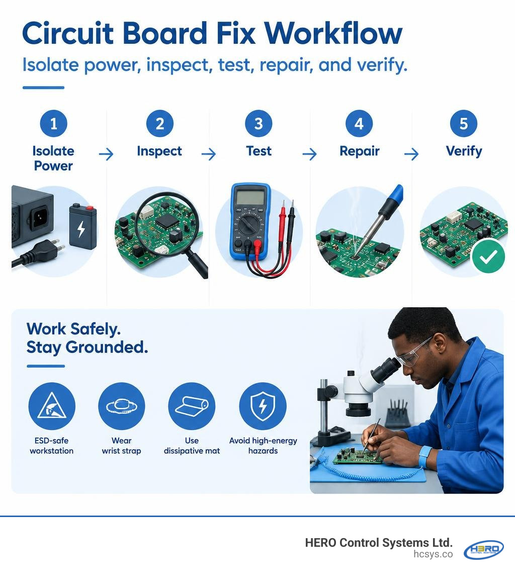
For a circuit board fix, disconnect power and the battery first. Note the device’s symptoms, then inspect the board for loose connectors, burnt parts, leaking capacitors, corrosion, and broken traces. On a board that is safe to handle, use a multimeter to check suspected connections and shorts with power off. Repair only the fault you can identify, then check your work before a controlled power-on test.
Stop if the board connects to mains power or contains large capacitors. Unplugging it may not remove the shock risk. For a utility or mining operation, a careful diagnosis can also help avoid replacing a board that is still repairable.
I’m Eng. Cephas Kalembo, founder and CTO of HERO Control Systems Ltd. in Lusaka. My work in PCB design and industrial electronics repair shapes this circuit board fix guide, from the first inspection through post-repair testing.
Preliminary Diagnostics and Safety Before You Begin
Before grabbing a soldering iron or turning on diagnostic equipment, safety and preparation must come first. High-energy electronics harbor hazards that can damage hardware or cause severe physical injury. Modern printed circuit boards are densely packed, sensitive to electrostatic discharge (ESD), and prone to collateral damage if tested incorrectly.
Always set up an ESD-safe workstation. Wear an antistatic wrist strap connected to a verified ground, and work on a dissipative mat. A tiny static discharge—imperceptible to your finger—can punch a microscopic hole through the gate oxide of a sensitive integrated circuit (IC), turning a simple repair into a cascade of failures.
When dealing with power supplies, motor drives, or appliance control boards, the primary bulk filter capacitors can store lethal direct current (DC) voltages long after mains disconnection. Never touch the leads or attempt to measure resistance on an energized board:
- Disconnect all AC mains cords and external DC power supplies.
- If working on battery-powered devices like modern laptops, disconnect the internal battery harness immediately.
- Measure the voltage across large electrolytic capacitors using a digital multimeter (DMM) set to DC volts.
- If residual charge remains, safely discharge each capacitor across its terminals using a ceramic power resistor (such as a 1 kΩ, 10-watt cement resistor) for several seconds. Never short the leads directly with a screwdriver blade, which causes arcing, pits the board, and stresses component internals.
If your board is protected by an acrylic, polyurethane, or silicone conformal coating, you will need to gain electrical access to your test nodes. Rather than stripping the entire board with harsh chemical solvents, apply targeted thermal or mechanical techniques. Piercing-style needle probes can penetrate thin coatings without damaging underlying copper. For localized component replacement, apply a drop of targeted chemical stripper or use a micro-abrasive swab to clear the pads before soldering. To understand how non-destructive testing fits into a comprehensive troubleshooting process, technicians frequently reference methods for power-off PCB testing to evaluate circuits without subjecting damaged silicon to live power.
Visual Inspection Techniques Under Magnification
Never underestimate the power of a careful visual survey. Industry experience shows that a rigorous visual inspection can uncover up to 60 percent of all circuit board defects before a single meter probe touches a test point.
Using an optical stereo microscope or a high-definition digital inspection camera, systematically scan the board in an overlapping grid pattern:
- Solder Joints: Look for cold solder joints (dull, grainy appearances), cracked joints around heavy through-hole parts like transformers and inductors, and accidental solder bridges across fine-pitch IC pins. A solder bridge acts like an uninvited shortcut, routing current into places it was never designed to go.
- Multilayer Ceramic Capacitors (MLCCs): Examine surface-mount decoupling capacitors for subtle hairline fractures or chip-outs. Microscopic mechanical flex cracks can eventually lead to catastrophic internal short circuits.
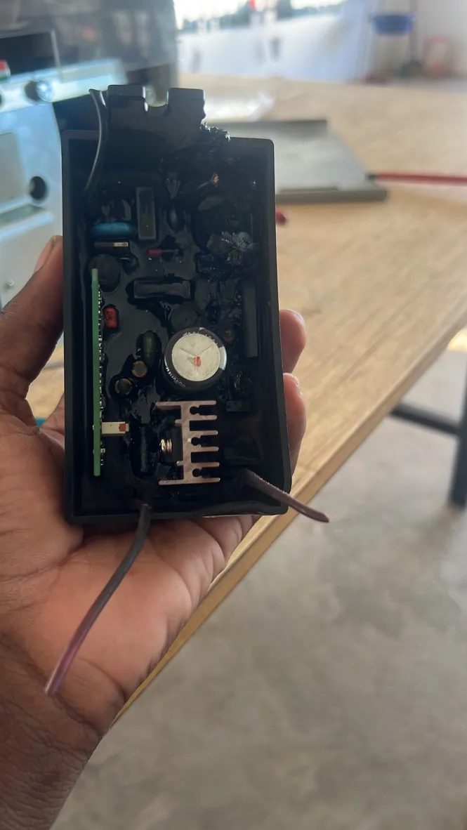
- Resistors and Diodes: Inspect for carbonization, discoloration, flaking packaging, or charred PCB substrate beneath passive components, indicating sustained overcurrent.
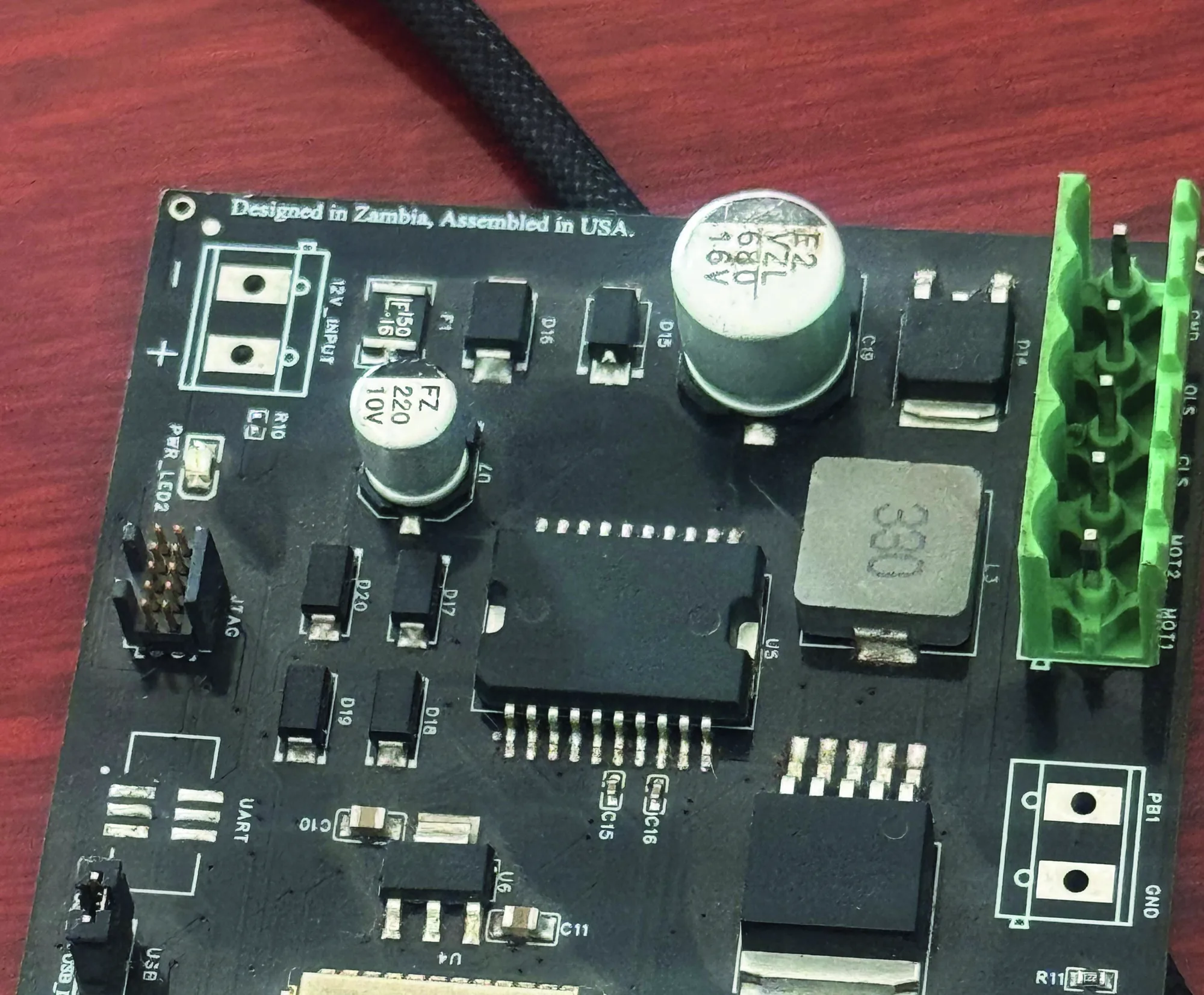
- Electrolytic Capacitors: Check the top vent stamps for doming or bulging. Inspect the base where the rubber bung seats against the board for crusty electrolyte residue, corrosion, or foul-smelling fishy odors.
Power-Off Testing and V-I Signature Analysis
Once visual anomalies are logged, begin passive testing without applying power to the device. Power-off electrical triage protects sensitive logic ICs from destructive overcurrent scenarios caused by rail-to-rail shorts.
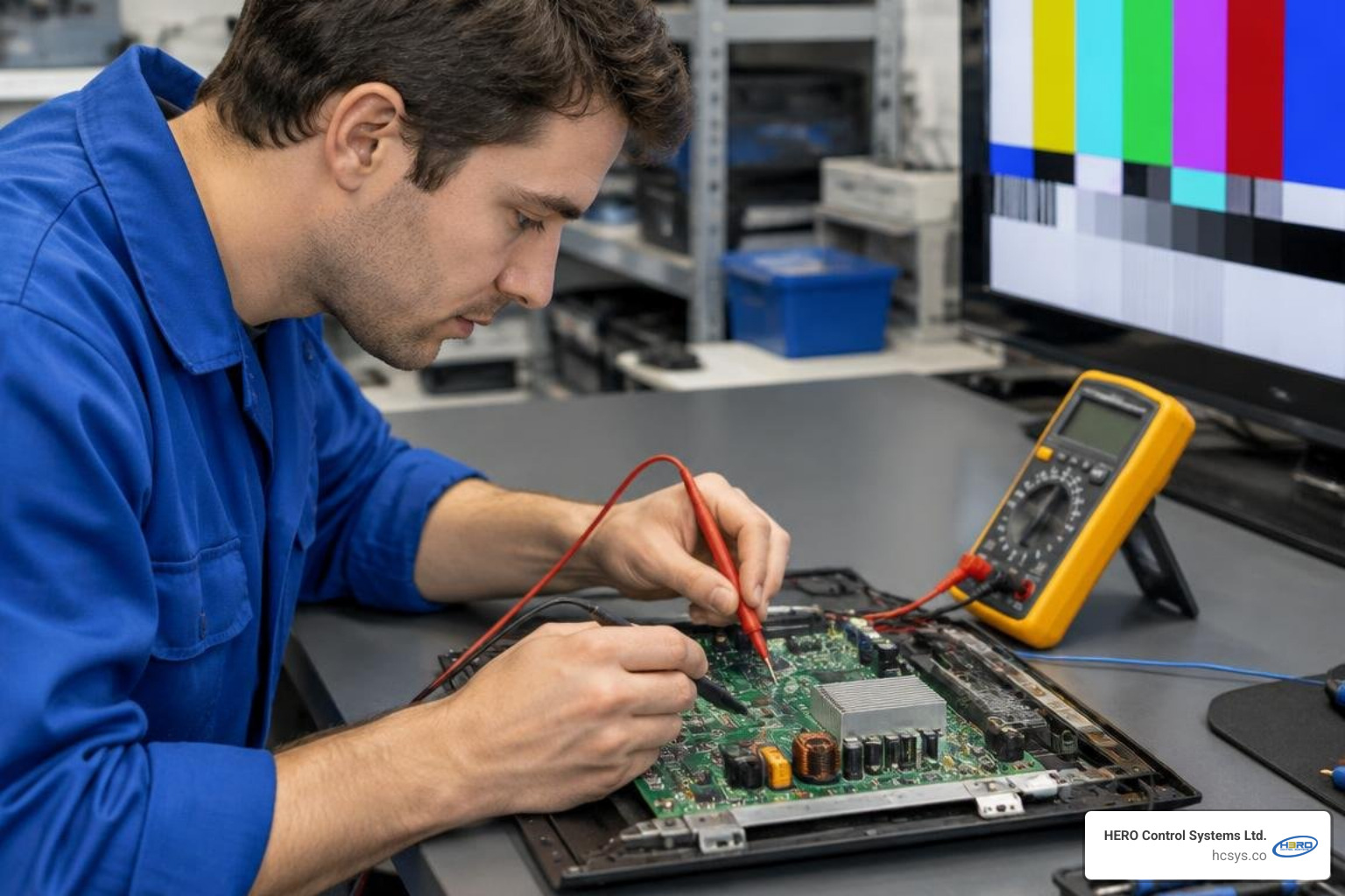
Start with a DMM in continuity or low-resistance mode. Measure the resistance across the main DC power rails (e.g., 12V, 5V, 3.3V, 1.8V, and core rails) relative to system ground. In healthy boards, power rails show a transient low reading that steadily climbs into kilo-ohms or mega-ohms as bulk bypass capacitors charge up from the meter's low-current probe circuit. A steady reading below 1 Ω typically points to an absolute short circuit.
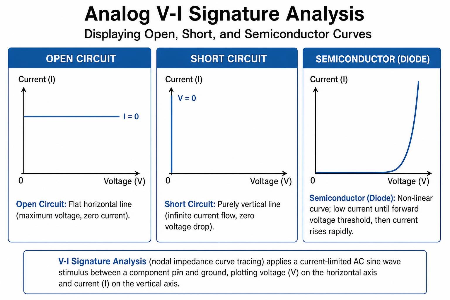
For advanced unpowered triage, professional repair engineers utilize Analog V-I (Voltage-Current) Signature Analysis, also known as nodal impedance curve tracing. By applying a current-limited AC sine wave stimulus between a component pin and ground, the instrument graphs voltage on the horizontal axis and current on the vertical axis:
- Pure Resistance: Displays as a diagonal line whose slope reflects the resistance value.
- Dead Short Circuit: Displays as a purely vertical line (infinite current flow, zero voltage drop).
- Open Circuit: Displays as a flat horizontal line (maximum voltage, zero current).
- Semiconductors (Diodes, Transistors, IC Protection Diodes): Produce characteristic "hockey stick" or elbow-shaped knee curves representing P-N junction forward-voltage thresholds.
- Capacitive/Inductive Elements: Yield elliptical or circular signatures due to phase shift between current and voltage.
By comparing V-I signatures against a known-good board or identical adjacent circuits (such as redundant input channels), you can isolate leaky semiconductor junctions and internally damaged ICs without ever powering up a compromised board.
Advanced Fault Isolation: Locating Hidden Shorts and Leakage
When a power rail exhibits a dead short to ground, finding the single culprit among dozens of parallel decoupling capacitors, clamping diodes, and integrated circuits can feel like searching for a needle in a copper-plated haystack. Applying full board power in this condition often trips power supply protection circuits or destroys upstream buck converters.
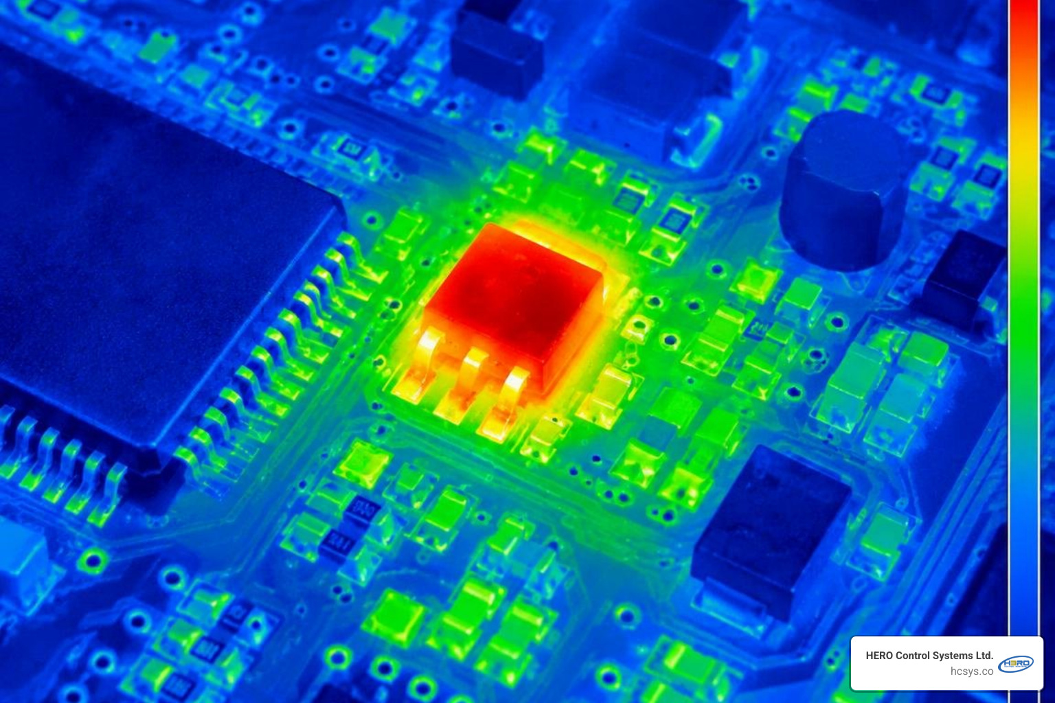
Instead, technicians apply the low-voltage current injection method. This approach forces current through the low-resistance fault path to generate localized dissipation without exceeding the maximum voltage tolerance of delicate silicon:
- Set a precision DC bench power supply to a very low voltage—never exceed the nominal rail voltage (typically 0.8V to 1.0V for low-voltage logic or CPU core rails, and no more than 3.3V for standard I/O rails).
- Set the current limit conservatively (start around 1.0 A, gradually increasing up to 2.0 A to 3.0 A if needed).
- Connect the negative supply lead securely to the primary ground plane.
- Solder or firmly clamp the positive supply lead to the shorted power rail pad.
- Apply current and monitor thermal changes across the PCB surface to identify where energy is being converted into heat.
Carefully managing current-injection limits and monitoring thermal dissipation ensures safe fault isolation without blowing delicate logic gates.
Thermal Mapping and Freeze Spray Techniques
Locating the component that dissipates injected energy can be done using thermal cameras or aerosol cooling agents:
- Thermal Imaging Cameras: A radiometric thermal imager with macro focusing can detect minute temperature deltas as low as 0.1 °C. A shorted MLCC or damaged MOSFET will light up as an intense bright hot spot on the thermal map within seconds of current injection, isolating the failed component immediately.
- Freeze Spray Evaporation (The Low-Cost Method): If a thermal camera is unavailable, coat the suspect area of the PCB with an aerosol electronics freeze spray (or 99% pure isopropyl alcohol). As the liquid coats the components in a frosty or wet film, inject current. The defective component with internal dielectric breakdown will warm up first, rapidly melting the frost or boiling away the alcohol layer while adjacent healthy components remain frosted.
Common root causes exposed by these techniques include:
- MLCC Dielectric Breakdown: Sub-micron cracks in ceramic dielectric layers that fuse into solid carbon/metallic conductive bridges under high voltage transients.
- Conductive Anodic Filament (CAF) Growth: Electro-chemical copper migration along the glass fibers inside the FR4 substrate, creating insidious internal interlayer short circuits under humid operating conditions.
Voltage Rail Mapping and Automated Test Equipment
In multi-rail microelectronic systems, power distribution networks (PDNs) follow strict sequencing. When power-management ICs (PMICs) sense a fault on an auxiliary buck rail, they latch off the entire system within milliseconds to prevent silicon destruction.
Mapping these rails requires a structured schematic trace:
- Trace voltage paths through switching inductors, current-sense shunts, and linear low-dropout (LDO) regulators.
- Take 4-wire Kelvin resistance measurements across successive nodes along the trace; the point with the lowest milliohm reading relative to ground marks the physical vicinity of the short.
- In smart equipment and connected electronics, engineers frequently address complex multi-bus issues and power architecture anomalies by referencing custom IoT hardware and firmware diagnostics to isolate whether a failure stems from a power silicon fault or a corrupted bootloader holding a power rail disabled.
In high-volume repair depots, manual probing is augmented by Automated Test Equipment (ATE) such as flying probe systems and multichannel in-circuit functional testers. ATE setups can execute hundreds of automated nodal impedance tests, diode checks, and boundary-scan (JTAG) routines across complex bus lines in seconds, cutting diagnostic times by up to 70 percent compared to purely manual bench testing.
Step-by-Step Circuit Board Fix for Common Component Failures
Repairing a malfunctioning board requires choosing the right intervention for the diagnosed failure mode. The table below outlines standard industrial failure signatures and their corresponding corrective actions:
| Component / Failure Mode | Diagnostic Symptom | Diagnostic Tool | Standard Repair Method |
|---|---|---|---|
| Electrolytic Filter Capacitor | Bulging vent, high equivalent series resistance (ESR), power ripple | LCR Meter / ESR Meter | Desolder through-hole part; clear vias; install low-ESR, high-temperature replacement |
| Surface-Mount MLCC | Dead short (under 1 Ω) between VCC rail and ground plane | DMM Continuity / Thermal Imaging | Current injection, hot-air desoldering, pad cleaning, SMD replacement |
| Power MOSFET / Switching Transistor | Gate-to-drain puncture, thermal runaway discoloration | DMM Diode Mode / V-I Signature | Hot-air rework station, apply tacky flux, solder replacement matching RDS(on) and gate charge |
| Corroded Copper Trace | Open circuit, zero continuity between IC pins and passives | DMM Continuity / Microscope | Scrape mask to bare copper, bridge with enameled wire, seal with UV-cure solder mask |
| Blown Surface-Mount Fuse | Open circuit on main input rail after power surge | DMM Resistance Mode | Isolate downstream overcurrent short; replace fuse (never bridge with raw solder) |
Replacing Blown Capacitors and Surface Mount Components
Once the defective part is isolated, follow industry rework standards (such as IPC-7711/7721) to remove and replace components without lifting fragile copper pads.
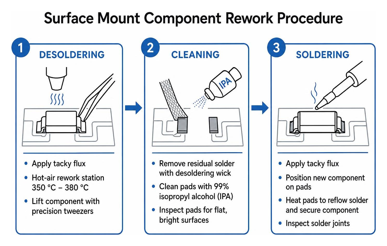
- Apply Tacky Flux: Coat the component leads with a high-grade rosin or no-clean tacky flux. Flux promotes uniform heat transfer and prevents oxidation during heating.
- Component Removal:
- For Through-Hole Parts: Use a temperature-controlled desoldering vacuum iron to remove solder from the barrel, or heat the pad with an iron while drawing molten alloy away using copper desoldering braid.
- For Surface-Mount Devices (SMD): Use a focused hot-air rework station set between 350 °C and 380 °C (depending on leaded vs. lead-free solder alloy) with medium airflow. Pre-heat the surrounding board area to 100 °C to prevent thermal shock and board delamination. Once the solder liquefies completely, lift the component with anti-magnetic precision tweezers.
- Site Preparation: Clean residual old solder using desoldering wick saturated with flux. Clean the pads thoroughly with 99% isopropyl alcohol (IPA) and inspect under magnification to ensure flat, bright surfaces.
- Soldering the New Part: Tin one pad with fresh solder, position the replacement component with tweezers, tack the first lead in place, align perfectly, and complete soldering of remaining terminals using a fine chisel or conical iron tip.
Trace Reconstruction: A Reliable Circuit Board Fix for Broken Connections
Liquid spills, battery acid leakage, and physical board stress frequently sever delicate surface traces. A systematic trace rebuild restores electrical connectivity and mechanical durability:
- Remove Contamination and Corroded Mask: Clean the area with distilled water and IPA to neutralize chemical residues. Using a micro-scalpel or fiberglass scratch brush under a microscope, carefully scrape away green solder mask to expose 1 to 2 mm of clean, bright copper on both sides of the break.
- Tin the Exposed Copper: Apply a dab of flux and lightly tin the exposed copper sections using a fine soldering tip.
- Bridge with Jumper Wire: For low-current signal lines, cut a section of fine enameled magnet wire (0.05 mm to 0.1 mm diameter / 38-44 AWG). For power-distribution traces, select insulated jumper wire sized to safely handle the maximum operational amperage of the rail. Solder the jumper securely across the exposed, tinned trace anchors.
- Insulate and Structurally Anchor: Clean off all residual flux. Apply a thin layer of UV-curable solder mask over the repaired trace and cured jumper wire. Expose the area to a 365 nm UV light source for 30 to 60 seconds until rock-hard. In high-vibration applications, reinforce the area with high-temperature polyamide (Kapton) tape.
For complex liquid ingress recoveries, thorough ultrasonic cleaning, pad reconditioning, and meticulous trace verification under magnification are essential steps before repowering.
Post-Repair Verification and Controlled Power-On Sequence
Never plug a newly repaired board straight into a wall outlet or unprotected power harness. A controlled power-on protocol prevents catastrophic failures if a secondary, undetected fault remains on the board.
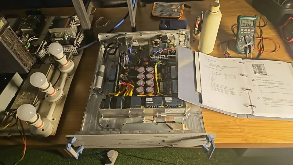
Execute post-repair validation in strict sequence:
- Passive Cold Resistance Checks: Repeat DMM continuity and resistance measurements from every primary power rail to ground. Confirm that the previous short-circuit condition is fully cleared and that rail impedance matches expected normal values.
- Current-Limited Bench Power-Up: Connect the board to a lab DC power supply. Set the supply's current limit just slightly above the device’s normal idle draw. Slowly dial up the voltage to the nominal operating level while watching the ammeter. If current draw spikes abruptly, cut power immediately to investigate.
- Thermal Verification: Monitor the board with your thermal camera or non-contact IR thermometer for 5 to 10 minutes during initial power-up. Ensure that power-management ICs, microcontrollers, and linear regulators maintain stable, expected operating temperatures (typically below 50 °C to 60 °C at idle).
- Signal and Functional Validation: Check oscillator clock signals with an oscilloscope, verify that reset lines transition from low to high cleanly, and measure secondary output voltages from internal switching buck regulators.
Technicians applying these systematic protocols in field environments rely heavily on hands-on industrial repair practices to guarantee that repaired control systems endure harsh operating conditions long after leaving the bench.
Economics of Repair: DIY, Professional Service, or Replacement
When electronics fail, equipment owners face a financial decision: repair the board at the component level, purchase a manufacturer replacement assembly, or discard the entire machine.
A widely accepted guideline in consumer and industrial sectors is the 50 Percent Repair Rule: if repairing a device costs less than half the price of buying a brand-new unit—and the equipment has not reached the end of its useful design lifespan—repair is the economically superior choice. For a detailed breakdown of repair economics and rights, consult this guide to consumer repair rights and cost evaluation.
Component-level repair yields massive savings:
- In consumer appliances, a technician might quote $250 to $450 to replace an entire refrigerator or washing machine control board. Replacing a failed $1.50 filter capacitor on that same board often resolves the issue in under an hour.
- In consumer electronics, a modular board swap can restore functionality quickly. For example, the community guide for Nintendo Switch Dock circuit board replacement demonstrates how modular hardware swaps keep devices out of landfills with modest mechanical effort.
- In industrial control systems, water utilities, and mining plants, replacement control cards are frequently obsolete or have multi-month lead times. Repairing and validating existing printed circuit boards keeps essential infrastructure operational while supporting sustainable repair and circular economy strategies.
When original equipment manufacturers discontinue hardware support, engineering teams can extend operating lifespans for decades, as demonstrated when reviving obsolete legacy control boards for municipal utilities.
When is a DIY Circuit Board Fix Feasible Versus Professional Replacement?
Determining whether to attempt a repair yourself or engage a specialized industrial repair lab depends on equipment complexity, safety risks, and tool availability:
- Good Candidates for DIY Repair: Single- or double-sided PCBs, through-hole capacitors, standard surface-mount passives (0805 packages or larger), broken wire leads, cracked solder joints on heavy connectors, and basic appliance control modules.
- When to Seek Professional Engineering Services:
- High-density boards featuring 6 to 12+ internal layers where internal power plane shorts cannot be reached with basic soldering irons.
- Ball Grid Array (BGA) packages, fine-pitch QFN ICs, and micro-scale components requiring precision optical alignment and calibrated hot-air reflow profiles.
- High-voltage inverters, high-power industrial motor drives, and safety-critical medical or automotive controllers where improper rework risks fires or personal injury.
- Firmware-locked or microcode-corrupted microcontroller boards requiring specialized programmer hardware and embedded engineering support.
Frequently Asked Questions About Circuit Board Repair
How can you fix a shorted circuit board without a thermal camera?
You can reliably isolate short circuits without an expensive thermal camera by using the freeze spray evaporation technique or milliohm resistance mapping.
With freeze spray, coat the suspect circuit area in aerosol coolant until a layer of frost forms. Inject low-voltage, current-limited power (1.0V, 1.5A to 2.0A) from a bench DC supply into the shorted rail. The shorted component dissipates localized heat, rapidly melting the frost while surrounding parts stay cold.
Alternatively, use a multimeter with a 4-wire Kelvin milliohm probe setup to measure track resistance along the rail; the point exhibiting the absolute lowest resistance relative to ground marks the physical location of the shorted component.
What cleaning solutions are safe for repairing corroded circuit boards?
Use high-purity 99 percent isopropyl alcohol (IPA) for general flux removal, oil breakdown, and moisture displacement. High-purity IPA evaporates quickly and leaves zero conductive residue behind.
For severe corrosion caused by alkaline battery leaks, coffee, or acidic liquid spills, first spot-clean the affected area with distilled water (optionally agitated with a soft antistatic nylon brush) to dissolve and flush away ionic salts. Follow immediately with a generous rinse of 99% IPA to displace all moisture, then thoroughly dry the assembly in a warm, dry environment or convection drying cabinet for 24 to 48 hours before applying power. Never use household glass cleaners, acetone, or general chlorinated solvents on circuit boards, as they dissolve plastic connectors, strip silkscreen printing, and leave conductive chemical films behind.
Is it safe to bridge a broken trace with jumper wire?
Yes, bridging a broken trace with a jumper wire is fully approved under IPC-7721 rework standards, provided you adhere to proper electrical and mechanical guidelines:
- Ampacity Matching: Ensure the jumper wire gauge can safely carry the maximum operating current of the circuit. For sensitive data and logic signals, 30 to 36 AWG enameled magnet wire is suitable. For heavy power rails, select thicker stranded or solid-core hookup wire sized to the rail's rated amperage.
- Insulation: Use enameled or Teflon-insulated wire to avoid accidental contact with adjacent vias, pads, or test points.
- Mechanical Anchoring: Secure the wire flat against the PCB substrate using drops of UV-curable solder mask, electronics-grade silicone, or polyamide tape to prevent vibration-induced solder joint fatigue.
Conclusion
Resurrecting dead circuit boards is one of the most rewarding pursuits in modern engineering. By combining disciplined, power-off visual and unpowered testing with controlled fault isolation like current injection, you can systematically pinpoint root causes, replace defective components, rebuild damaged copper traces, and return expensive machinery to active duty.
Taking the time to diagnose and fix electronics at the component level saves money, reduces electronic waste, and protects vital infrastructure from supply-chain delays. When you encounter high-density multilayer boards, obsolete legacy hardware, or custom industrial assemblies that demand advanced diagnostics, partnering with experienced design and rework engineers ensures long-term operational success. Explore our professional PCB design and engineering support to discover how HERO Control Systems Ltd. brings advanced electronics design, precision manufacturing, and component-level repair capabilities to organizations across the region.