Troubleshooting Common Faults in Modern HVAC Control Boards
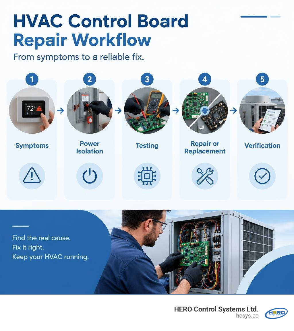
HVAC Control Board Repair Starts With a Safe Diagnosis
For HVAC control board repair, first confirm that the board is the fault. An unresponsive thermostat, a blower that runs nonstop, or flashing error codes can also point to a failed sensor, loose wire, or power problem. Record the error code and photograph the wiring. Then have a qualified technician isolate power, verify that stored voltage has discharged, and test the board and connected parts before deciding whether to repair or replace it.
This matters when an HVAC shutdown disrupts a site: replacing a board without finding the cause of failure can damage the new one.
I’m Eng. Cephas Kalembo, founder and chief technology officer of HERO Control Systems Ltd. My experience in PCB design and industrial electronics repair shapes the diagnostic approach to HVAC control board repair in this guide.
Common Symptoms and Diagnostic Indicators of Board Failure
Modern climate control systems depend entirely on printed circuit boards (PCBs) to orchestrate everything from ignition sequencing and compressor staging to variable-speed blower modulation. When this master controller glitches, the symptoms can range from subtle timing delays to total operational paralysis.
Before jumping to conclusions, technicians must systematically evaluate what the equipment is doing versus what it is commanded to do. Here are the most prevalent field symptoms:
- Unresponsive Thermostat Input: The user interface or wall thermostat calls for heating or cooling (sending 24 VAC across terminals like R, W, Y, or G), but the board fails to energize the corresponding relays.
- Continuous Blower Operation: A stuck relay contact or shorted triac on the PCB frequently forces the indoor blower motor to run nonstop, even when the system is set to "Off" or idle.
- Intermittent Shutdowns and Lockouts: Thermal stress, cracked solder joints, or degraded electrolytic capacitors cause random resets, dropping system communication mid-cycle.
- Diagnostic LED Flash Codes: Modern boards feature status LEDs that blink specific heartbeat or fault patterns. Cross-referencing these flashes against technical documentation—such as guidance on how to find the right HVAC control board—is essential to isolate input faults from internal logic errors.
- Total Power Loss (Dead Board): When line voltage enters the board and the transformer outputs 24 VAC, but the status LEDs remain completely dark, an open onboard trace, blown secondary fuse, or failed switching power supply is often present.
Essential Safety Protocols and Tools for HVAC Control Board Repair
Circuit board diagnostics involve both line voltage and stored direct-current energy. Rushing into an electrical enclosure without following strict safety protocols risks severe shock, arc flash, and component destruction.
At HERO Control Systems, we treat every board service call with industrial-grade safety standards. Before unclipping a single harness, follow these non-negotiable rules:
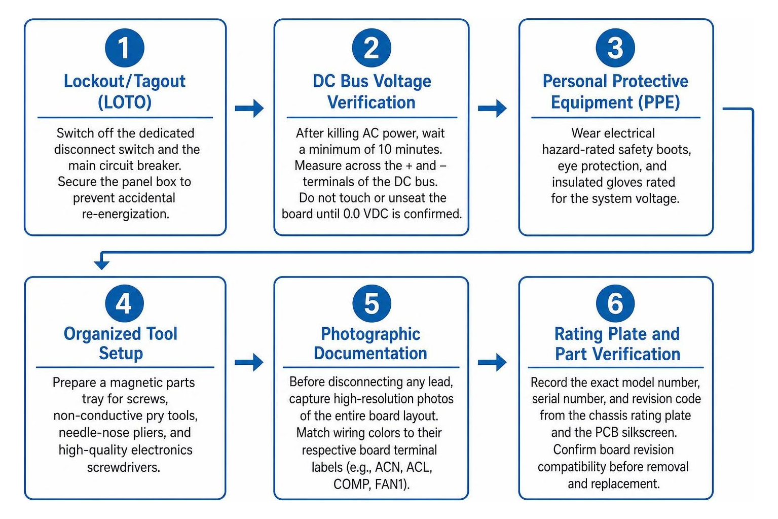
- Lockout/Tagout (LOTO): Switch off the dedicated disconnect switch and the main circuit breaker. Secure the panel box to prevent accidental re-energization.
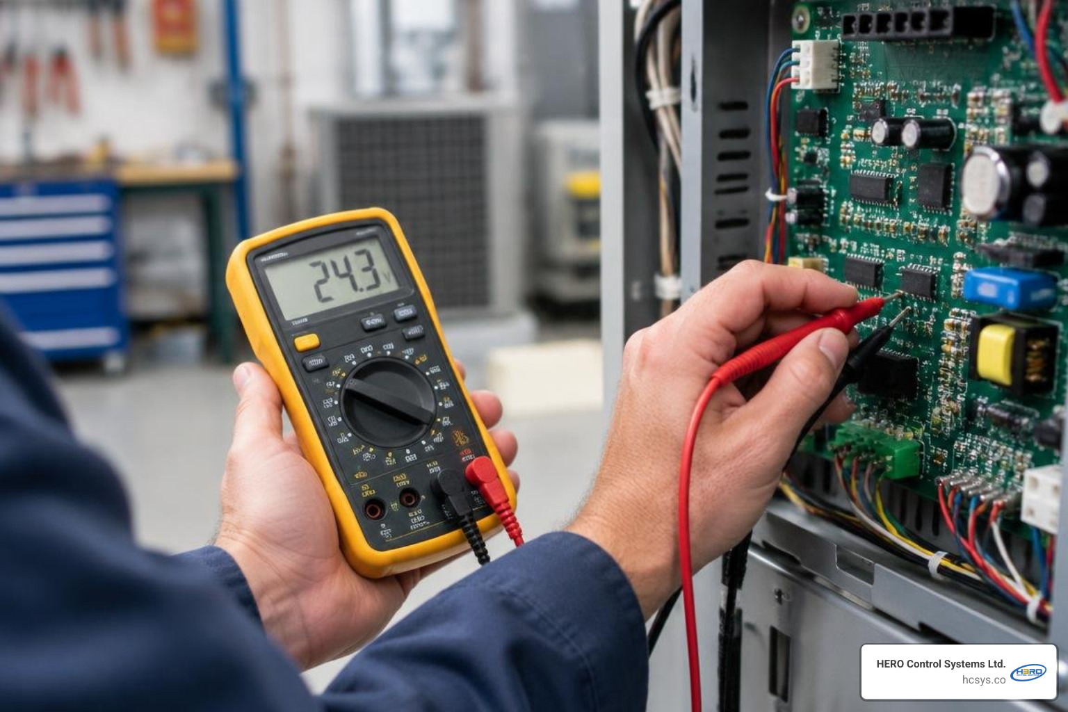
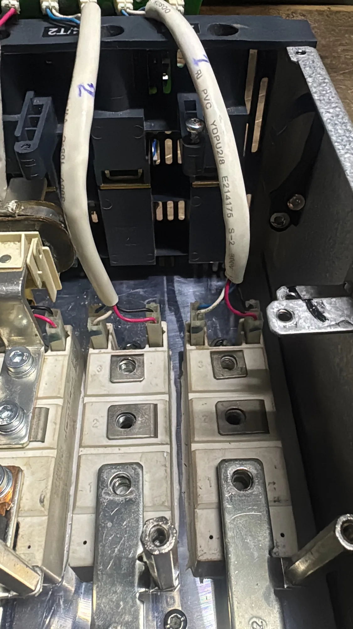
- DC Bus Voltage Verification: Inverter-driven mini-split and heat pump systems house massive capacitor banks. After killing AC power, wait a minimum of 10 minutes. Then, using a Category III or IV digital multimeter, measure across the positive (+) and negative (-) terminals of the DC bus. Do not touch or unseat the board until the meter confirms 0.0 VDC.
- Personal Protective Equipment (PPE): Wear electrical hazard-rated safety boots, eye protection, and insulated gloves rated for the system voltage.
- Organized Tool Setup: Prepare a magnetic parts tray for screws, non-conductive pry tools, needle-nose pliers, and high-quality electronics screwdrivers.
When handling hardware damaged by power surges, our specialized industrial repair benches use static-dissipative mats and grounded wrist straps to prevent electrostatic discharge (ESD) from frying sensitive microcontrollers.
Step-by-Step Diagnostic and Replacement Procedures
Replacing an electronic control card requires precision. An installation completed in haste can ruin a replacement part within milliseconds of startup.
1. Photographic Documentation and Labeling
Before disconnecting any lead, capture high-resolution photos of the entire board layout from multiple angles. Modern multi-stage boards contain dozens of similar molex plugs, sensor leads, and high-voltage spade terminals. Match wiring colors to their respective board terminal labels (e.g., ACN, ACL, COMP, FAN1).
2. Rating Plate and Part Verification
Record the exact model number, serial number, and revision code from the chassis rating plate and the PCB silkscreen. Manufacturers frequently release mid-generation hardware revisions where pinouts or firmware configurations shift. Official technical guides, such as the proper board replacement guide for GREE mini-splits, emphasize that board revisions are not always backwards compatible.
3. Harness Disconnection
Unplug wire harnesses by gripping their plastic housings and releasing their locking tabs—never yank on the wire strands. Use needle-nose pliers gently for tight spade terminals to avoid cracking the surrounding PCB solder pads.
For complex installations where proprietary firmware or field-programmable controllers are involved, reviewing our expert answers on PCB, firmware, and IoT repair helps demystify controller architectures.
Advanced Diagnostics and Component-Level HVAC Control Board Repair
When an original board is scarce, obsolete, or costly, component-level troubleshooting allows technicians to pinpoint and repair the exact circuit failure.
- Filter Board and Fuse Checks: Inspect the high-voltage ceramic fuses and low-voltage blade fuses. If a fuse is blown, inspect the metal-oxide varistors (MOVs) and filter capacitors for surge damage before replacing it.
- Electronic Expansion Valve (EEV) Inspection: A shorted EEV stepper motor coil is a notorious board-killer. Before installing a repaired or new board, use a multimeter to measure the resistance of each EEV coil winding to ground and across pin pairs. A grounded or shorted coil will immediately destroy the output driver chips on the new board.
- DC Bus Load Isolation: If the DC bus voltage sags significantly under load, disconnect secondary components (inverter compressor, outdoor fan motor) one at a time. If the voltage recovers after removing a specific plug, that motor or actuator is dragging down the circuit.
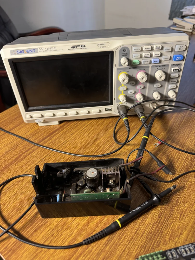
- Solder Joint Reflow and Trace Repair: Inspect the underside of the PCB under magnification. High-current relays running electric heat strips or blower fans frequently suffer from localized solder fatigue. Resoldering cracked joints or bridging burnt copper traces restores normal electrical pathways.
In industrial and municipal facilities, legacy control boards often face sudden obsolescence. Our real-world case study on rebuilding a discontinued control card for Lusaka Water illustrates how component-level restoration saves mission-critical infrastructure from premature retirement.
Reinstallation, Thermal Paste Application, and Error Code Verification
Installing the board correctly ensures long-term reliability and protects expensive power electronics like Intelligent Power Modules (IPMs).
Thermal Paste Application
Inverter power modules generate considerable heat. If your board mounts directly against an aluminum heat sink or refrigerant-cooled cold plate, old thermal compound must be completely cleaned away using 99% isopropyl alcohol. Apply a thin, uniform layer of electronics-grade thermal paste across the component surface. Never use automotive compounds, brazing flux, or silicone adhesives.
Torque Sequence
Treat mounting screws like the lug nuts on an automotive wheel. Fasten screws in an inner-to-outer crisscross pattern, applying even torque to prevent flexing the fiberglass substrate or creating uneven thermal contact with the heat sink.
Setting Jumpers and DIP Switches
Carefully inspect the original board for physical jumper caps and miniature DIP switch positions. These toggle system capacity, defrost timing, communication protocols, and electric heat staging. Missing or misplaced jumper caps trigger immediate diagnostic lockouts.
Common Post-Installation Error Codes
When commissioning the system, reference technical publications such as the Friedrich and Kühl room air conditioner service manual to interpret error alerts quickly:
| Error Code | Primary Root Cause | Diagnostic & Resolution Step |
|---|---|---|
| H5 | IPM Overcurrent / Phase Error | Check for reversed ACL/ACN wiring, verify compressor winding resistance, and confirm heat sink contact. |
| E6 | Communication Fault / Ground Short | Verify low-voltage interconnect wiring; inspect EEV stepper motor coils for shorts to chassis ground. |
| C4 | Missing Capacity Configuration | Ensure the capacity configuration jumper cap or resistor pack was transferred from the old board. |
| C5 | Jumper Cap / DIP Switch Mismatch | Verify all DIP switch toggle positions match the indoor/outdoor chassis model configuration. |
Repair vs. Replacement: Evaluating OEM Boards and Component-Level Repair
Facility managers and technicians often face a crossroads: pay for a brand-new factory module, or send the failed unit for component-level refurbishment.
| Factor | OEM Board Replacement | Component-Level Board Repair |
|---|---|---|
| Typical Cost | 100% (Baseline expense) | 30% to 70% of replacement cost |
| Availability | Subject to supply chain backorders and obsolescence | Unaffected by factory parts discontinuation |
| Lead Time | Days to months depending on dealer inventory | Standard turnaround of around 10 working days |
| Warranty Protection | Typically 90 days on electronic replacement parts | Comprehensive 1-year to 3-year repair warranty |
| System Compatibility | Plug-and-play (if exact revision matches) | Exact fit; preserves existing wiring, harness plugs, and firmware |
When local supply chains lack specialized modules, engineering teams skilled in custom PCB design in Zambia can trace schematics, upgrade stress points, and fabricate drop-in electronic replacements.
Deciding Between OEM Upgrades and HVAC Control Board Repair
If an HVAC unit is less than five years old and the manufacturer provides an affordable, readily available board with active warranty support, purchasing an OEM replacement is often straightforward.
However, if your commercial building automation or HVAC system has surpassed 10 years of service, original boards are frequently discontinued. A call to an equipment distributor often ends with a recommendation to replace the entire mechanical system for tens of thousands of dollars.
In these situations, component-level repair eliminates long supply chain delays and extends the operational lifespan of the existing plant. When equipment needs updated interface logic or protective circuit redesign, utilizing custom electronics design bridges the gap between legacy machinery and modern controls.
Frequently Asked Questions About HVAC Control Board Repair
How much money can be saved by repairing an HVAC board instead of replacing it?
Repairing an existing control board generally saves between 30% and 70% compared to purchasing a new OEM module or undertaking a premature system overhaul. For large commercial chillers and packaged rooftop units, avoiding a full equipment replacement saves substantial capital expenditure.
What causes an HVAC control board to burn out immediately upon replacement?
Immediate board failure is usually caused by an external short circuit that was never resolved during diagnosis. The most common culprits include shorted electronic expansion valve (EEV) coils, failed fan motor windings, reversed line-voltage wiring (ACN and ACL), loose ground wires, and ungreased heat sink surfaces causing immediate IPM thermal overcurrent trips.
How long does a professional component-level board repair typically take?
Standard bench repair turnaround for industrial and HVAC electronic modules is approximately 10 working days. This timeframe allows technicians to complete thorough initial testing, component desoldering, trace repair, conformal coating reapplication, and live-load quality assurance testing.
Conclusion
An HVAC control board is the nerve center of modern environmental control systems. Diagnosing faults accurately requires methodically separating external wiring and sensor problems from true circuit board failures. By enforcing strict electrical safety protocols, applying thermal paste properly, and validating all connected loads, technicians protect equipment and ensure long-term reliability.
When rare or discontinued control boards fail, component-level electronics restoration offers a practical, cost-effective alternative to costly equipment replacements. Explore our comprehensive industrial electronics services to see how HERO Control Systems Ltd delivers engineering-grade circuit repairs, custom hardware design, and embedded system solutions to keep your critical infrastructure running.