How to program a bare ATmega328P with an Arduino Uno
When a design moves from an Arduino prototype to its own circuit board, the microcontroller goes onto the board bare: no USB chip, no bootloader and often no crystal. Something still has to load its settings and firmware. An Arduino Uno can do that job. With the ArduinoISP sketch loaded, it becomes an in-system programmer (ISP) that writes to a bare ATmega328P on a breadboard.
This is the procedure we use at Travis Labs to program chips in small batches for boards we design and build in Lusaka. It sets each chip to run on its internal 8 MHz clock with no bootloader, flashes the firmware, and proves the chip runs on its own before it goes onto a board.
What you need
- An Arduino Uno (or a clone with an ATmega328P) and its USB cable.
- A breadboard, jumper wires and the target chip: an ATmega328P in the 28-pin DIP package.
- A 10 kΩ resistor, a 100 nF capacitor and a 10 µF electrolytic capacitor.
- For the test: an LED and a 330 Ω resistor.
- Only if a chip turns out to expect a crystal: a 16 MHz crystal with two 22 pF capacitors, or the clock wire described below.
- The Arduino IDE (for the ArduinoISP sketch) and avrdude, the command-line programmer. avrdude comes with both the Arduino IDE and PlatformIO, or can be installed on its own.
The wiring
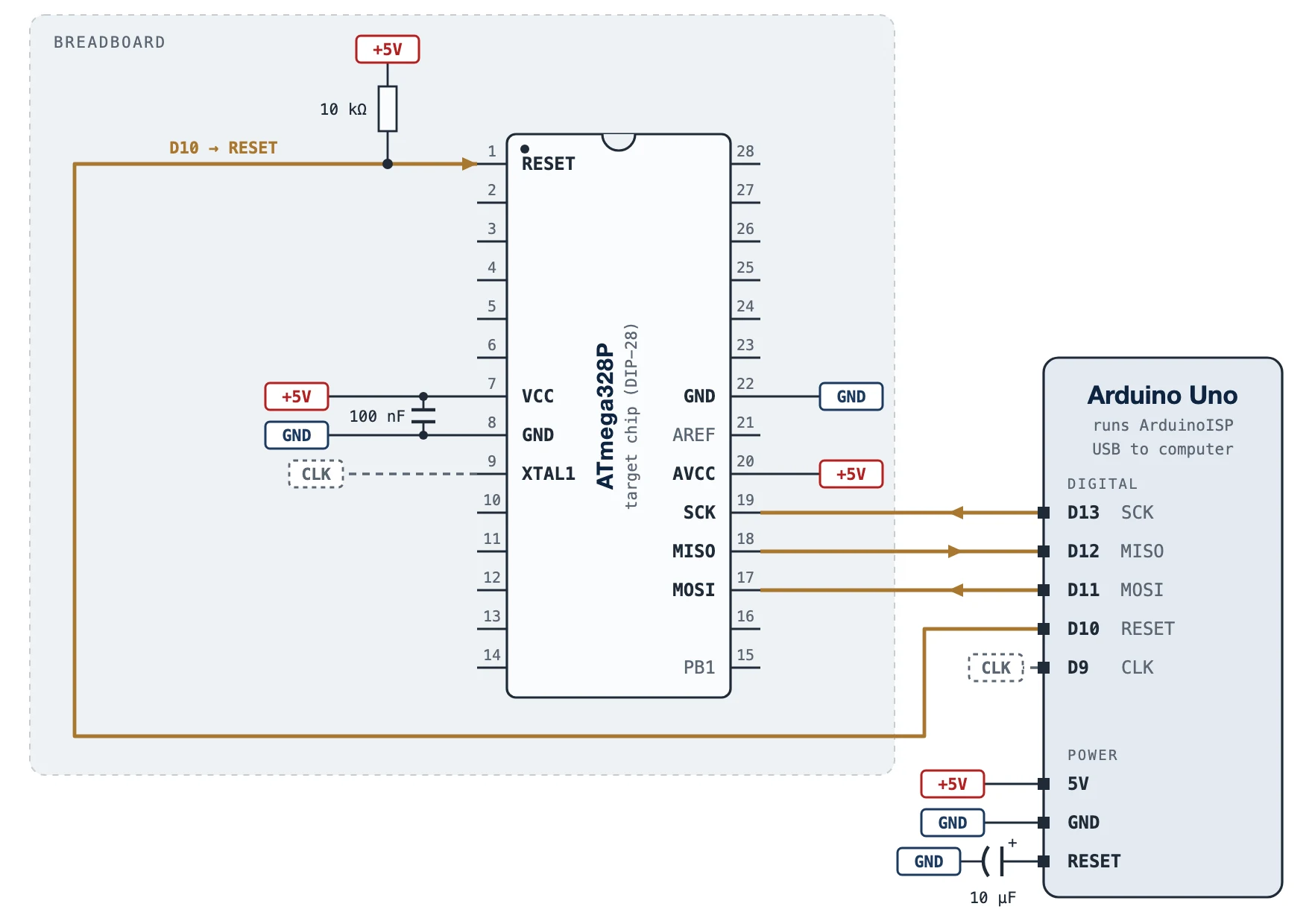
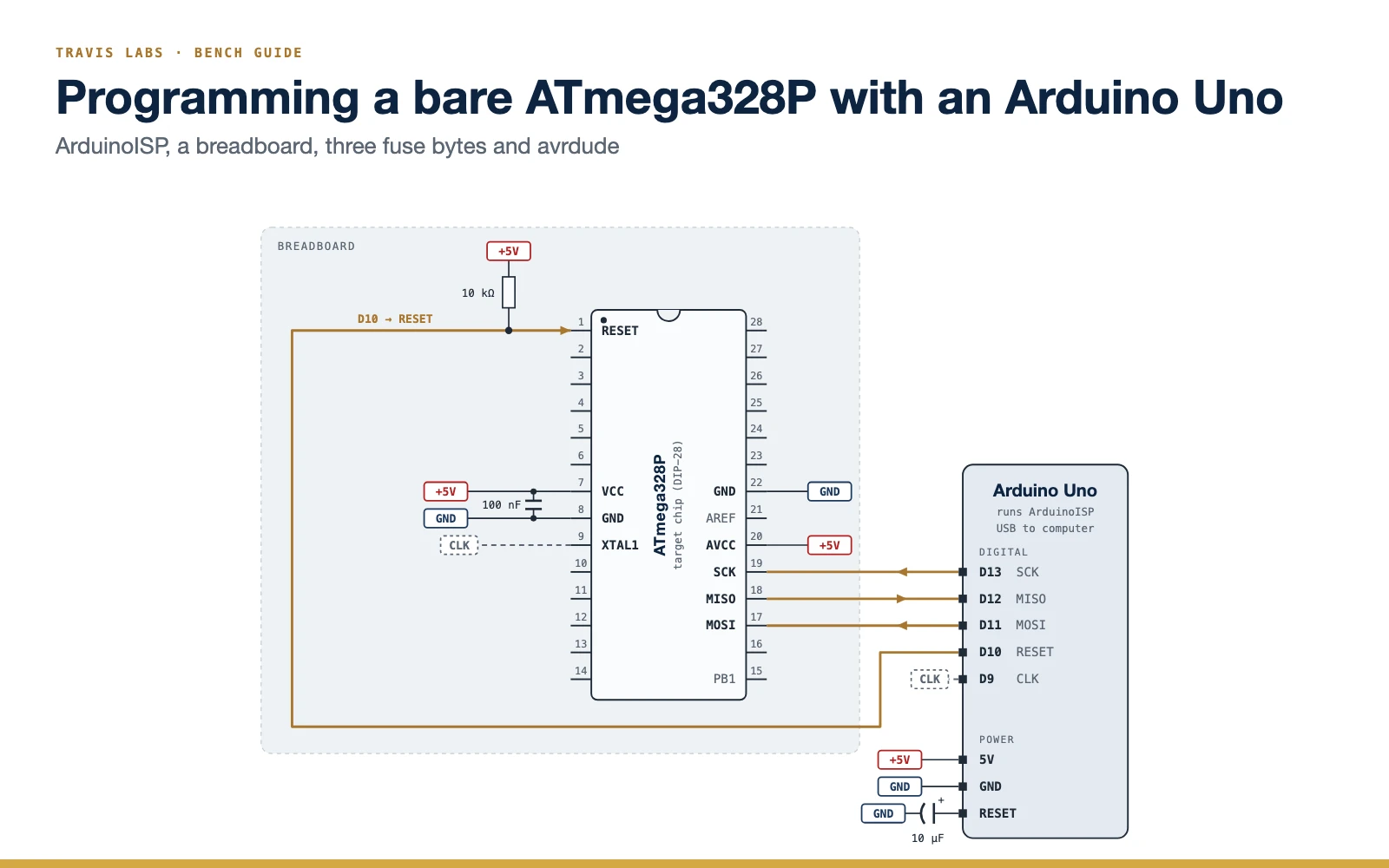
Place the chip the way it is drawn: notch up, pin 1 top left, pins counting down the left side and back up the right.
| Uno | Chip pin | Signal |
|---|---|---|
| D13 | 19 | SCK |
| D12 | 18 | MISO |
| D11 | 17 | MOSI |
| D10 | 1 | RESET |
| 5V | 7 and 20 | VCC and AVCC |
| GND | 8 and 22 | Ground |
| D9 | 9 | Clock, only if needed |
Add a 10 kΩ resistor from pin 1 to 5 V, a 100 nF capacitor across pins 7 and 8, close to the chip, and a 10 µF capacitor on the Uno itself, from RESET to GND with the + leg on RESET.
Wire pin 20. Many breadboard guides leave AVCC unconnected. The ATmega328P datasheet requires it to be connected to VCC even when the analogue-to-digital converter is not used, so connect it, and connect the second ground on pin 22 too.
Does the chip need the clock wire?
A chip can only be programmed if it is running, and it runs on whatever clock its low fuse byte selects. That depends on where the chip came from:
| Chip as bought | Low fuse | Clock wire |
|---|---|---|
| Blank, from Microchip or a distributor | 0x62: internal 8 MHz ÷ 8 = 1 MHz | Not needed |
| Sold with an Arduino bootloader, or pulled from an Uno | 0xFF: expects a 16 MHz crystal | Needed |
| Already programmed with the settings in this guide | 0xE2: internal 8 MHz | Not needed |
A blank chip at 1 MHz is not a problem: ArduinoISP programs slowly enough for it. A chip that expects a crystal looks dead without one. Either fit a 16 MHz crystal with two 22 pF capacitors on pins 9 and 10, or let the Uno supply the clock: make two edits to the ArduinoISP sketch before uploading it, and add the D9 wire. Pin 9 then carries an 8 MHz clock instead of driving the heartbeat LED.
// 1. Move the heartbeat LED off pin 9
#define LED_HB 6          // was 9

// 2. Add at the very top of setup()
pinMode(9, OUTPUT);
TCCR1A = (1 << COM1A0);
TCCR1B = (1 << WGM12) | (1 << CS10);
OCR1A = 0;                // 16 MHz / 2 = 8 MHz on pin 9
Set up the rig (once per session)
- Load ArduinoISP onto the Uno. Plug in only the Uno, with no capacitor and nothing on the breadboard. In the Arduino IDE open File → Examples → 11.ArduinoISP → ArduinoISP, choose the Arduino Uno board and its port, and upload. Use the edited version above if you need the clock wire.
- Fit the 10 µF capacitor between the Uno's RESET and GND, + leg on RESET, with USB unplugged. It stops the Uno resetting every time avrdude opens the port. Take it out whenever you want to upload a new sketch to the Uno itself.
- Wire the breadboard as in the figure, but leave the target chip out for now.
- Give the avrdude command a short name. Paste this into the terminal (macOS or Linux), replacing the port with your Uno's. It is usually
/dev/cu.usbmodem…on a Mac and/dev/ttyACM0on Linux; on Windows, use the full command with the Uno'sCOMport each time.
isp() { avrdude -c stk500v1 -P /dev/cu.usbmodemXXXX -b 19200 -p m328p "$@"; }On our bench, avrdude 7.2 gave verification mismatches with ArduinoISP and version 6.3 did not. If you see mismatches on writes that should be fine, try another avrdude version before blaming the wiring.
Program each chip
Step 1: Insert the chip and read it
With USB unplugged, press the chip into the breadboard, notch up. Plug in USB, then read the chip's signature and fuses. This only reads.
isp -U lfuse:r:-:h -U hfuse:r:-:h -U efuse:r:-:hExpect Device signature = 0x1e950f, the ATmega328P's own, and three fuse bytes. Compare the first with the table above. A signature of 0x000000, with the wiring checked, means the chip is not running: it is waiting for a crystal, so add the clock wire.
Step 2: Burn the fuses
isp -U lfuse:w:0xE2:m -U hfuse:w:0xD9:m -U efuse:w:0xFD:mExpect 1 bytes of lfuse verified, and the same for hfuse and efuse. The chip now runs on its internal 8 MHz clock, so remove the clock wire if you used it.
| Fuse | Value | What it sets |
|---|---|---|
| Low | 0xE2 | Internal 8 MHz RC clock, no ÷8, 65 ms start-up delay |
| High | 0xD9 | No bootloader, so the firmware starts at power-up; ISP programming stays enabled |
| Extended | 0xFD | Brown-out reset at 2.7 V |
Some avrdude versions show the extended fuse as 0x05 instead of 0xFD; only its lowest three bits are used, so the two are the same setting.
Check the high fuse before you press Enter. A high fuse that disables the reset pin or turns on debugWIRE locks the chip out of ISP programming, and only a high-voltage programmer or a debugWIRE tool can recover it. 0xD9 does neither. A wrong low fuse is less serious: a chip set for a crystal it does not have only looks dead, and the clock wire brings it back.
Step 3: Flash the firmware
The firmware must be built for the clock the chip now runs on, 8 MHz. In PlatformIO set board_build.f_cpu = 8000000L. In the Arduino IDE, use a board package that offers the ATmega328P on its internal 8 MHz clock with no bootloader, such as MiniCore, and export the compiled binary. Then write the .hex file:
isp -U flash:w:firmware.hex:iExpect a line reporting how many bytes of flash were verified.
Step 4: Unplug, lift the chip, test it
Unplug USB before pulling the chip, and before inserting the next one. Test it on its own, then mark it and fit it to its board. For the next chip, go back to step 1.
Test the chip on its own
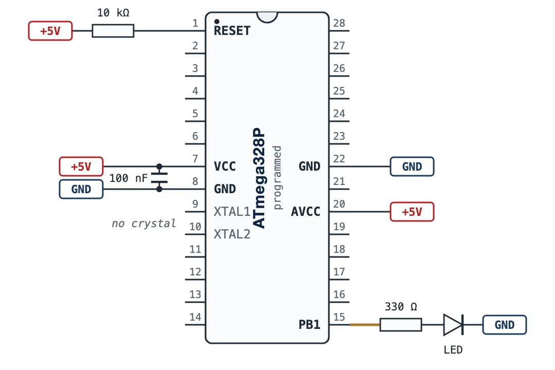
This proves the chip runs on its own clock and that the firmware's timing is right. A simple first firmware for the test is a blink on Arduino pin 9 (chip pin 15): one second on, one second off.
void setup() { pinMode(9, OUTPUT); }
void loop() { digitalWrite(9, HIGH); delay(1000); digitalWrite(9, LOW); delay(1000); }| What the LED does | What it means |
|---|---|
| 1 second on, 1 second off | Fuses and firmware are right. The chip is ready. |
| About 2 seconds on, 2 off | The firmware was built for 16 MHz. Rebuild it for 8 MHz and flash it again. |
| About 8 seconds on, 8 off | The low fuse still divides the clock by 8 (0x62). Burn the fuses again. |
| Never lights | The chip is not running: the low fuse still expects a crystal, or flashing failed. Put it back on the rig and read the fuses. |
Why internal 8 MHz and no bootloader?
- Fewer parts. No crystal and no load capacitors on the board, and pins 9 and 10 are free for other use.
- Instant start. With no bootloader, the firmware runs as soon as power arrives, instead of after a bootloader's wait.
- Safe on a sagging supply. Brown-out reset holds the chip in reset below about 2.7 V instead of letting it run on an unreliable supply, which matters wherever mains dips and outages are common.
- The trade-off is accuracy. The internal oscillator is factory-calibrated, but the datasheet allows it to be up to ±10% off and it drifts with temperature and voltage. That is fine for switching relays and timing seconds; it is not good enough for a clock, precise timing or fast serial links. Use a crystal for those.
Tips for programming in batches
- A 28-pin ZIF (zero insertion force) socket on the breadboard saves the chip's legs, and your time, over a long batch.
- Read the fuses back after burning them, and keep a short log per batch.
- Mark each programmed chip, for example with a dot of paint, so finished and blank chips never mix.
- Always unplug USB before inserting or removing a chip.
Travis Labs designs circuit boards and firmware in Lusaka and builds them in small batches. See our electronics design work, read about PCB design in Zambia, learn this hands-on on our electronics course, or contact us.