Revive Your 3D Printer with an Anet A8 Motherboard Replacement
Choosing an Anet A8 Motherboard Replacement
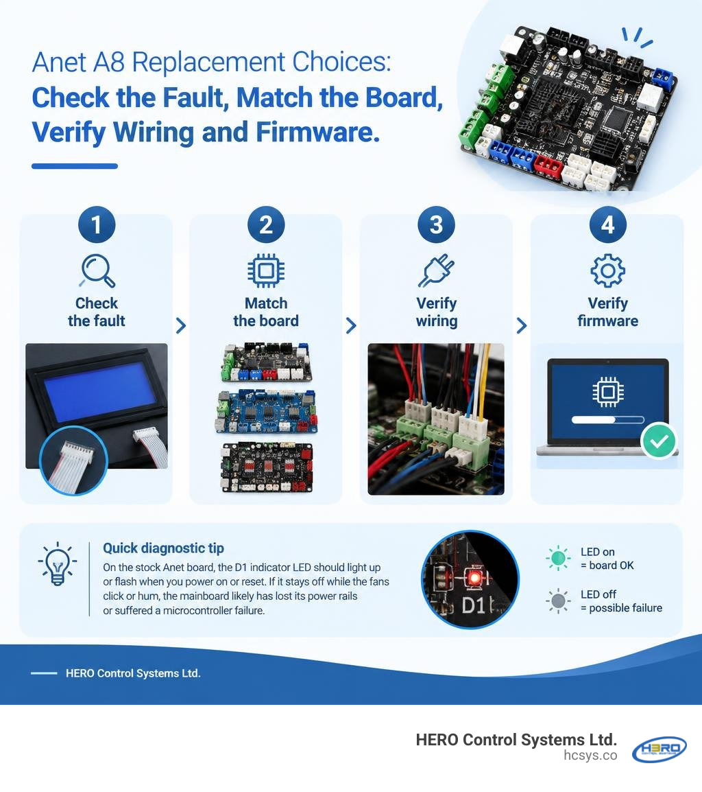
For an Anet A8 motherboard replacement, start with a board that matches your printer’s power supply and connectors. A matching Anet board is usually the simplest swap. An A8 Plus board or a 32-bit controller may also work, but neither should be treated as a drop-in replacement: check the pinout, LCD support, mounting, and firmware before buying.
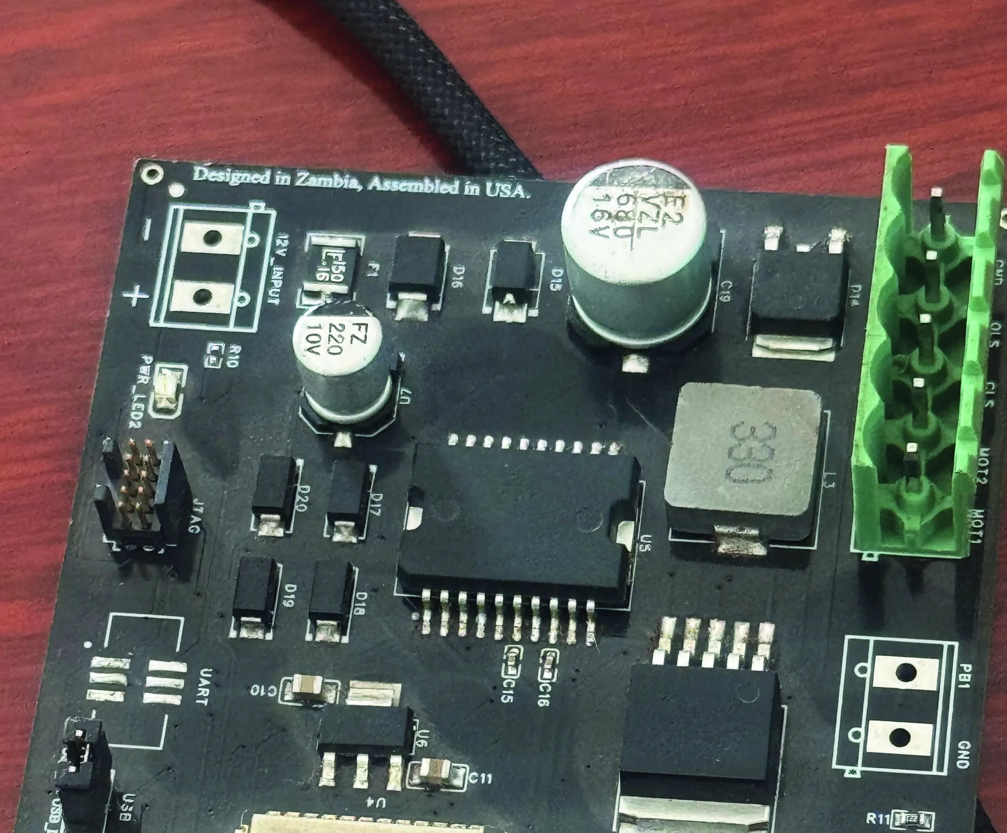
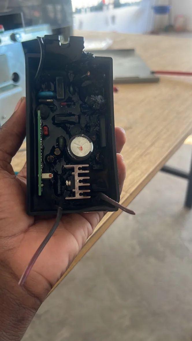
Check the fault first. A blank or block-filled LCD can come from a loose ribbon cable, not just a failed motherboard. If the board has burned terminals, do not power it on again. Inspect the wiring and heated-bed circuit before fitting a new board; an external MOSFET can reduce the load on the board’s bed output.
I’m Eng. Cephas Kalembo, founder and CTO of HERO Control Systems Ltd. in Lusaka, with over a decade of experience in PCB design, embedded firmware, and electronics repair. I bring that experience to this guide on anet a8 motherboard replacement, starting with how to tell whether the board is actually at fault.
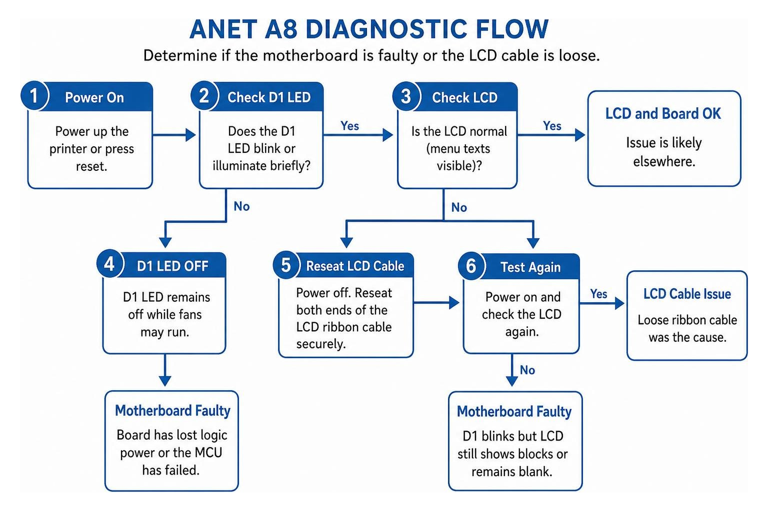
Diagnosing Mainboard Failure vs LCD Display Issues
Before tearing down your 3D printer, confirm that the controller board is genuinely defective. A printer that fails to boot or displays weird visual artifacts might simply be suffering from a loose ribbon cable, a corrupted EEPROM, or a blown external fuse.
The fastest hardware diagnostic checkpoint on the stock Anet board is the onboard D1 indicator LED. When you power on the machine or trigger a hardware reset, the D1 LED should illuminate or flash briefly as the bootloader handshakes with the ATmega microcontroller. If you power up the machine and the D1 LED remains completely off while the fans click or hum faintly, the mainboard has likely lost its primary logic power rails or suffered a catastrophic microcontroller failure.
Seeing white blocks on LCD screen after Anet A8 power up is one of the most common user complaints. This symptom typically indicates that the LCD controller is receiving basic power, but no serial initialization data is arriving from the main processor. If resetting the board does not make D1 blink, the firmware is not executing.
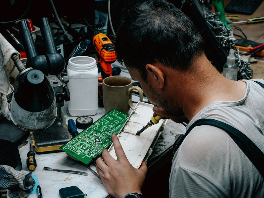
Another critical failure scenario involves thermal runaway. The stock firmware on older Anet boards lacked active thermal runaway protection. If an extruder heater cartridge slips out or a thermistor wire breaks, the board may pump continuous current into the hotend, melting the carriage and destroying the onboard traces. When traces lift or show discoloration, component-level repair is rarely worth the safety risk compared to installing a fresh board. You can learn more about how component failure manifests by reviewing real-world logs from Fixing A8 ANET 3D v1-5 Mainboard | Electronics Repair And Technology News.
Identifying Stepper Motor Driver Short Circuits
The stock Anet v1.0 through v1.7 boards feature integrated A4988 (or 4988ET) stepper motor driver chips soldered directly to the PCB. If an axis binds mechanically, or if a stepper motor cable is disconnected while the machine is energized, these driver ICs can suffer internal junction shorts.
When a 4988ET driver fails short, it often pulls the 5V logic rail down to ground, causing excessive current draw on the order of 0.5 amps across the low-voltage circuitry. You can test for this with a multimeter:
- Disconnect main 12V power from the printer.
- Set your multimeter to measure resistance (ohms).
- Measure across the inputs and outputs of the 5V linear regulator (designated as Q4 or LM7805 on many revisions). A healthy regulator circuit exhibits high input resistance, whereas a blown driver IC often pulls the resistance on the 5V rail down to around 35 ohms or lower.
- If you have bench equipment, power the board via USB and touch each driver chip gently. A shorted driver will rapidly heat up to scorching temperatures even when idle.
At HERO Control Systems, we see these exact failure patterns daily in our industrial electronics troubleshooting lab, where voltage rails collapse due to surface-mount driver breakdowns.
LCD Screen Artifacts and Ribbon Cable Checks
Do not replace your mainboard if the issue is simply signal degradation between the controller and the display. The Anet A8 uses either a 5-button 2004 character LCD or an upgraded 12864 graphic LCD screen.
Both screens rely on multi-conductor IDC ribbon cables that are sensitive to electrical noise generated by unshielded stepper motor leads. Follow these steps to verify your display:
- Turn off power and reseat the 10-pin ribbon cable at both the motherboard header (LCD/J3) and the back of the screen display board.
- Check the ribbon cable for physical pinches or sharp crimps caused by the printer's acrylic frame edges.
- If the screen displays solid white rectangular boxes across the first and third rows, reconnect the cable several times to scrape away surface oxidation on the pins.
- If the D1 LED blinks during boot but the screen remains garbled, test the LCD on a known working setup or swap the ribbon cable before ordering a replacement board.
Top Options for an Anet A8 Motherboard Replacement
When shopping for a replacement board, you can choose an original OEM replacement, an upgraded Anet A8 Plus board, or an advanced 32-bit controller. Each board offers distinct benefits regarding firmware support, silent motor operation, and thermal safety.
| Motherboard Model | Processor Architecture | Supported Voltage | Stepper Driver Setup | Typical Price Range (USD) | Best Suited For |
|---|---|---|---|---|---|
| Anet OEM v1.7 Mainboard | 8-bit ATmega1284P | 12V only | Integrated A4988 | $42 – $65 | Exact drop-in replacement with no wiring changes |
| Anet A8 Plus Integrated Board | 8-bit ATmega2560 | 12V – 24V | Integrated A4988 / Silent | $65 – $75 | Native compatibility with larger current handling |
| Aftermarket 32-Bit Controller | 32-bit ARM Cortex-M | 12V – 24V | Socketed TMC2208/2209 | $70 – $92 | Maximum print quality, silent movement, safety |
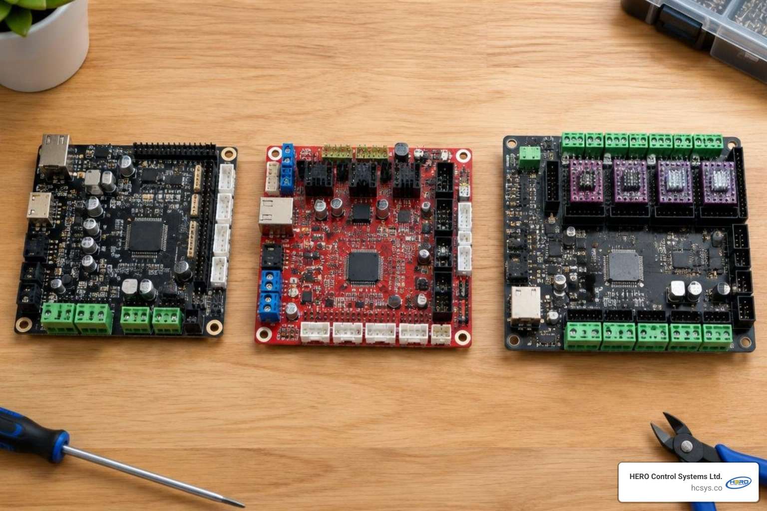
Choosing an Anet A8 Motherboard Replacement: Stock vs Upgraded Boards
If you want a painless repair with zero modifications to your wiring harness, the Anet OEM v1.5 or v1.7 board is the simplest route. You unplug the old board, screw down the new board using the existing acrylic mounting holes, and plug the connectors back into their matching locations. However, stock boards retain the original design limitations: soldered drivers, limited memory space for modern firmware features, and strained screw terminals for the heated bed.
If you opt for the Anet A8 Plus mainboard, you gain an integrated USB interface, better thermal layout, and support for dual Z-axis outputs alongside wider voltage ranges (12V to 24V). Pin configurations for auxiliary modules can change between versions; for example, interfacing wireless modules on older v1.5 boards required desoldering zero-ohm resistors R52 and R53, whereas v1.7 boards routed signals directly to standard headers. You can see how these board revisions evolve by reviewing the hardware pinout modifications documented for embedded controllers.
32-Bit Controller Alternatives and Stepper Driver Flexibility
For significant performance and acoustic improvements, modern 32-bit controller boards are the premier upgrade path. These boards feature socketed stepper driver slots that accept Trinamic silent drivers (such as the TMC2208 or TMC2209).
Advantages of 32-bit boards include:
- Silent Operation: StealthChop technology eliminates high-frequency motor whine during printing.
- Improved Thermal Management: Better onboard copper pour distributions handle PWM heater loads without excessive heat build-up.
- Safety Buffers: Dedicated optocouplers and ESD protection prevent damaged limit switches from destroying the central processor.
- Expandability: Dedicated ports for auto-bed leveling sensors (BLTouch/3DTouch), filament runout sensors, and neopixel lighting strips.
When building specialized control systems or upgrading older machines, our team handles these kinds of hardware overhauls through our custom PCB integration services, ensuring industrial-grade wiring and clean signal paths.
Step-by-Step Guide to Installing an Anet A8 Motherboard Replacement
Replacing the motherboard is a straightforward process if you take systematic precautions. Keep a roll of electrical tape, a Phillips screwdriver, wire strippers, and a set of labeling tags on hand.
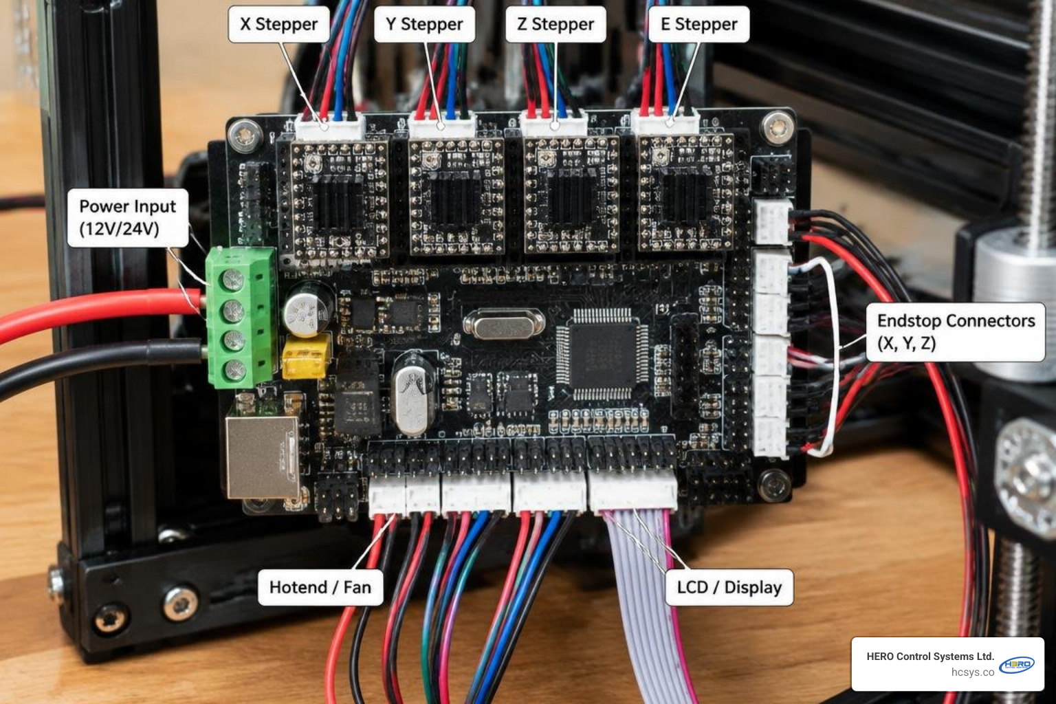
Preparing Wiring and Essential MOSFET Upgrades
The original Anet A8 draws approximately 10 to 12 amps through its heated bed circuit at 12 volts (roughly 120 to 144 watts). Passing that continuous current through budget PCB screw terminals often leads to melted plastic and charred copper contacts.
Before mounting your new board, install an external MOSFET module to isolate high-current bed heating from the logic board:
- Disconnect Power: Unplug the main power supply from the AC wall outlet. Never work on live 12V or 110V/220V wiring.
- Label Every Cable: Take high-resolution photos of your existing board. Tag each wire pair: Hotend (E0), Heated Bed (HB), Part Fan, Extruder Motor (E), X Motor, Y Motor, Z Motors, and the three mechanical endstops (X-Min, Y-Min, Z-Min).
- Route the External MOSFET: Connect the heated-bed output terminals of your replacement motherboard to the signal input terminals on the external MOSFET module.
- Wire High-Current Power: Run dedicated 14 AWG flexible silicone wiring with insulated spade or ferrule crimps directly from the 12V power supply to the external MOSFET power input. Connect the bed heating element directly to the MOSFET output.
For comprehensive safety teardowns and structural recommendations, see the detailed notes on A8 HeatBed Upgrades.
Mounting and Calibrating the New Board
Once your wiring is safely prepped:
- Remove the Old Board: Unscrew the four corner mounting standoffs securing the damaged board to the acrylic frame.
- Secure the New Board: Align the new motherboard. If using an aftermarket board with a different footprint, print or fabricate an adapter mounting plate. Use non-conductive nylon washers or standoffs between the board and the frame to prevent mechanical flex and short circuits.
- Attach Stepper Connections: Plug in the 4-pin X, Y, Z, and E motor cables. Ensure the keyed headers align correctly; running a stepper motor backward simply requires flipping the connector orientation or updating a single setting in firmware.
- Connect Endstops and Thermistors: Wire the mechanical microswitches to their corresponding signal and ground pins. Connect the 100k NTC thermistors for both the hotend and heated bed. Thermistors are passive resistive sensors, meaning polarity does not matter, but limit switches must use the correct normal-open (NO) and common (COM) terminals.
- Double-Check DC Polarity: Verify that the main positive (+12V) and negative (GND) leads from the power supply are connected with correct polarity. Reversing these inputs will instantly destroy the onboard electrolytic capacitors and voltage regulators.
If you are developing custom enclosures or mounting hardware, our prototyping specialists at HERO Control Systems assist builders through our custom circuit design workflow.
Configuring and Flashing Marlin Firmware for Safety
Never run a newly installed motherboard on unverified stock firmware. Open-source Marlin firmware includes active thermal runaway protection, software endstop safety buffers, and refined PID tuning for both the hotend and heated bed.
Follow these steps to flash custom firmware to your replacement board:
- Download Marlin Source Code: Download the latest stable release of Marlin and the matching Configurations repository.
- Locate the Configuration Files: Find the configuration files for the Anet A8 (located under
config/examples/Anet/A8in the configurations archive) and copyConfiguration.handConfiguration_adv.hinto your coreMarlinsource folder. - Enable Thermal Runaway Protection: Open
Configuration.hin your IDE (such as VS Code with PlatformIO or the Arduino IDE) and ensure the following safety directives are uncommented and active:THERMAL_PROTECTION_HOTENDSTHERMAL_PROTECTION_BED
- Define Display Type: Verify that your LCD controller is defined. For the stock Anet screen, ensure
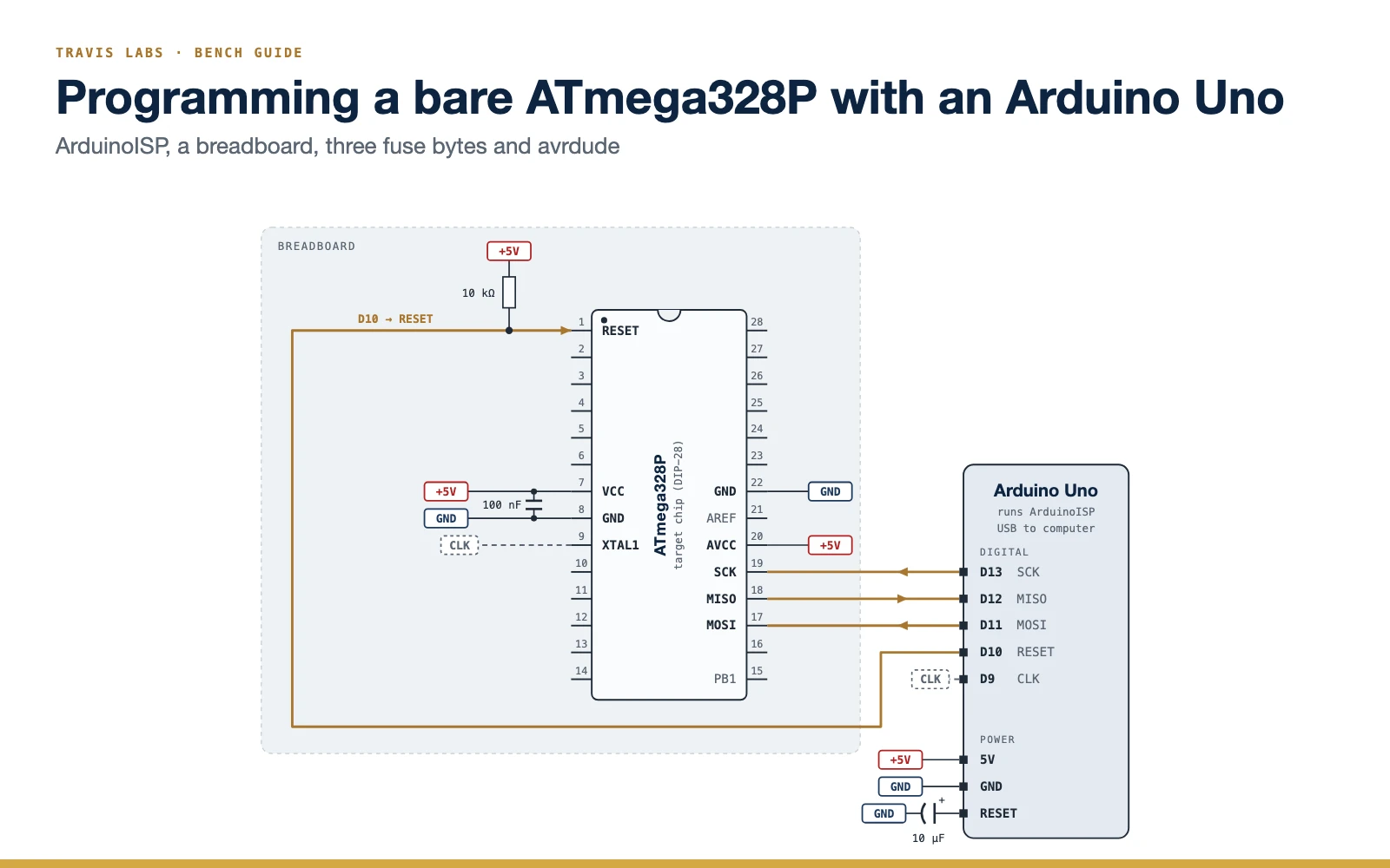
#define ZONESTAR_LCDor#define ANET_KEYPAD_LCDis enabled. If you upgraded to a graphic display, enable#define REPRAP_DISCOUNT_FULL_GRAPHIC_SMART_CONTROLLER. - Burn Bootloader (If Necessary): If flashing a factory-fresh ATmega1284P board that lacks a pre-installed bootloader, use an inexpensive USBASP programmer or an Arduino configured as an ISP to burn the Sanguino bootloader.
- Upload Firmware: Connect the board to your computer via USB, select the appropriate COM port and board target environment (e.g.,
sanguino1284pfor stock boards ormegaatmega2560for A8 Plus boards), and build/upload the firmware.
Best Practices to Prevent Future Mainboard Burnout
Once your printer is back up and running, implement basic preventative maintenance to ensure the hardware lasts for years without failure:
- Upgrade the Board Cooling Fan: The small stock fan included with basic acrylic kits moves very little air. Replace it with a 12V 5015 radial turbo blower directed across the stepper driver heatsinks to prevent thermal shutdown during 20-hour print jobs.
- Replace Bare Wire Ends with Bootlace Ferrules: Never insert bare, tinned, or frayed stranded copper wire directly into screw-terminal blocks. Over time, heat cycles cause solder to creep, resulting in loose connections, high resistance, and fire hazards. Crimp quality copper ferrules onto all high-current leads.
- Inspect the Power Supply Unit (PSU): The budget power supplies bundled with early DIY kits suffer from significant voltage sag under full load. Upgrading to a certified, enclosed 12V 30A (360W) power supply provides clean, ripple-free power to your board and motors.
- Step Down Peripheral Voltages Safely: If adding capacitive bed-leveling probes or custom 5V/7V sensors, use an external DC-DC buck converter to step down the 12V rail rather than overloading the mainboard's small onboard 5V linear regulator.
If you want to master these diagnostic and assembly techniques, we teach practical electronics, soldering, and embedded systems at our hands-on electronics engineering workshops in Lusaka.
Frequently Asked Questions About Anet A8 Motherboard Replacement
How do I know if my Anet A8 motherboard is completely dead?
A motherboard is considered completely dead if it fails to respond to power inputs and cannot establish serial communication over USB. Check these three items:
- Power Rails: Use a multimeter to measure the voltage across the main 12V terminal block and the 5V output of regulator Q4. If 12V is present but the 5V rail reads 0V, the regulator or an IC tied to it is dead.
- D1 LED Indicator: If the D1 LED does not flash when resetting the board, the processor is not executing code.
- USB Device Detection: Plug the board into a PC. If the device manager does not recognize the CH340 or FTDI USB-UART converter chip (or returns an "Unknown Device" hardware descriptor error), the board's logic circuitry has failed.
What is the cost of an Anet A8 motherboard replacement?
Replacement costs depend on the upgrade path you select:
- Component-Level Repair: If you have hot-air rework tools, replacement 4988ET driver ICs cost less than $5 for a multi-pack, allowing you to fix blown drivers cheaply.
- Stock Replacement Boards: Direct replacement OEM v1.7 boards typically cost between $42 and $65 online.
- Upgraded 32-Bit Systems: A modern 32-bit controller paired with four silent TMC2209 drivers and an external MOSFET ranges from $70 to $92.
Do I need to upgrade firmware after replacing the mainboard?
Yes. Even if you purchase an OEM replacement board that arrives with factory firmware pre-installed, you should immediately flash updated Marlin firmware.
Stock factory firmware on budget 8-bit boards often disables thermal runaway protection to save flash memory space. If a heater cartridge detaches or the thermistor fails, unpatched firmware will continuously drive the heating element, creating a severe fire hazard. Installing Marlin ensures modern safety features are fully enabled.
Conclusion
Carrying out an anet a8 motherboard replacement gives your trusted 3D printer a new lease on life while resolving the safety vulnerabilities of older controller designs. By systematically testing the D1 indicator LED, checking 4988ET motor drivers, installing an external heated-bed MOSFET, and flashing modern Marlin firmware, you can transform an unstable machine into a reliable workhorse.
At HERO Control Systems Ltd., we build, test, and service embedded systems with a complete end-to-end design capability in Lusaka, Zambia. Whether you need custom hardware design, industrial automation support, or PCB fabrication, explore our full range of expert electronics repair and engineering services to power your next project.