Why Arduino Is the Perfect Launchpad for Embedded Systems Engineering
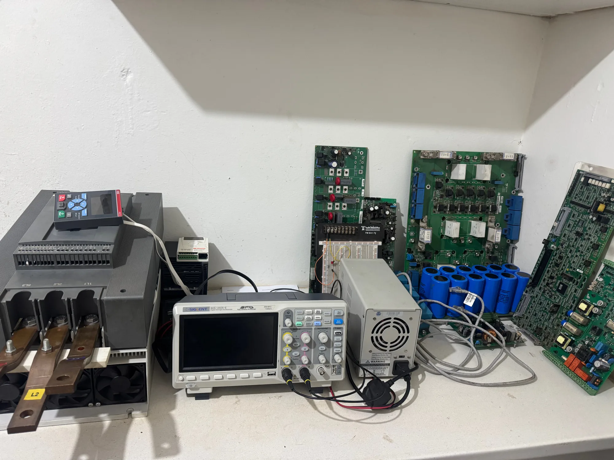
Why Arduino Is a Good Starting Point for Embedded Systems
An Arduino-based embedded system uses a small computer to read inputs, make a decision, and control an output. To start learning, connect an LED to an Arduino board, install the Arduino IDE, and upload a sketch that makes the LED blink. Then add a sensor and use its reading to control the LED. This gives you a working example of the same input-and-control pattern used in larger monitoring and automation projects.
A breadboard prototype is a place to test that pattern before designing hardware for a tougher setting, such as a utility or mining site.
I'm Eng. Cephas Kalembo, founder and CTO of HERO Control Systems Ltd. in Lusaka. I bring over a decade of PCB design, embedded firmware, and IoT work to this arduino embedded system guide.
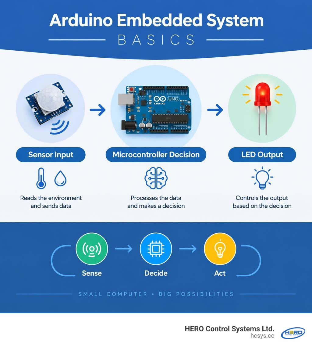
Core Architecture of an Arduino Embedded System
At its heart, an embedded system is a purpose-built combination of computer hardware and software designed to perform a dedicated function within a larger mechanical or electrical system. Unlike a personal computer running dozens of background tasks, a web browser, and an operating system, an embedded device executes a single focused control loop with predictable, deterministic timing.
In embedded engineering, we distinguish between microcontrollers (MCUs) and microprocessors (MPUs). Understanding this distinction is foundational for anyone stepping into hardware development.
| Feature | Microcontroller (MCU) | Microprocessor (MPU) |
|---|---|---|
| Primary Architecture | All-in-one chip (CPU, RAM, Flash, I/O peripherals integrated on a single silicon die) | Standalone CPU requiring external RAM, Flash storage, and peripheral interface ICs |
| Core Clock Speed | Typically 16 MHz to 480 MHz | Typically 800 MHz to 3.0+ GHz |
| Operating System | Bare-metal firmware or lightweight Real-Time Operating Systems (RTOS) | Full multi-tasking OS (e.g., Linux, Windows, Android) |
| Power Consumption | Extremely low (milliwatts to microwatts; ideal for batteries) | Moderate to high (watts to tens of watts; requires power management ICs) |
| Startup Time | Instantaneous (milliseconds to execute first instruction) | Extended boot sequence (seconds to minutes for OS kernel load) |
| Typical Role | Real-time sensor sampling, motor control, safety interlocks | High-level data processing, computer vision, web interfaces |
The classic Arduino platform standardizes the microcontroller environment, shielding developers from grueling register-level setup sheets while retaining direct access to raw physical pins.
Embedded Systems vs General-Purpose Computing
When you interact with a general-purpose laptop, you demand flexibility: opening spreadsheets, rendering 3D graphics, or running software updates. However, general-purpose operating systems introduce scheduling jitter. If an operating system spends several milliseconds servicing a background disk-write request, an attached safety relay might miss its cutoff threshold.
Embedded hardware operates under strict determinism. In our introduction to modern embedded programming, we explore how dedicated control loops guarantee that an incoming electrical trigger immediately produces an exact output response within microseconds. Whether monitoring the temperature of an industrial furnace or measuring fluid flow across a pipeline, an embedded system delivers guaranteed timing, high electrical reliability, and low power consumption.
Core Hardware Anatomy of an Arduino Embedded System
To see how an embedded board operates, let us break down the physical architecture of the ubiquitous Arduino Uno R3.
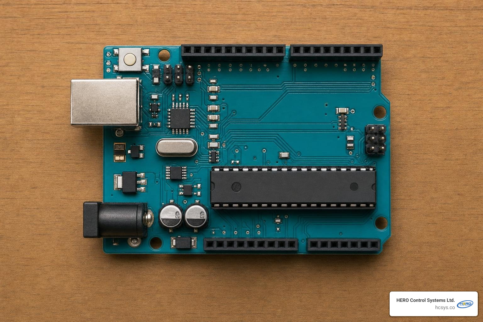
Every component on the board serves an explicit engineering function:
- The Microcontroller Core (ATmega328P): An 8-bit AVR RISC-based microcontroller running at a clock speed of 16 MHz. It provides 32 KB of In-System Programmable Flash memory for storing compiled code, 2 KB of SRAM for runtime variables, and 1 KB of EEPROM for non-volatile parameter storage.
- Power Regulation Stage: The board accepts unregulated 7 to 12 volts DC through a center-positive barrel jack or the VIN pin. An onboard low-dropout (LDO) linear regulator steps this voltage down to a clean, stable 5 volts DC for the MCU and logic headers, while an auxiliary regulator supplies 3.3 volts for low-voltage transceivers.
- Clock Source (Crystal Oscillator): A 16 MHz quartz crystal oscillator provides the precise heartbeat required by the CPU instruction pipeline, hardware timers, and serial UART baud clocks.
- Digital Input/Output Pins: 14 discrete pins (numbered 0 to 13) capable of reading or sinking/sourcing 5-volt logic signals. Six of these pins support hardware Pulse Width Modulation (PWM).
- Analog Input Stage: Six dedicated analog pins (A0 through A5) route external voltages into an internal 10-bit Successive Approximation Analog-to-Digital Converter (ADC), mapping signals between 0 and 5 volts into integer values ranging from 0 to 1023.
- USB-to-Serial Interface: A secondary programmed chip translates host computer USB data packets into standard Transmit (TX) and Receive (RX) TTL serial streams routed directly to the main microcontroller.
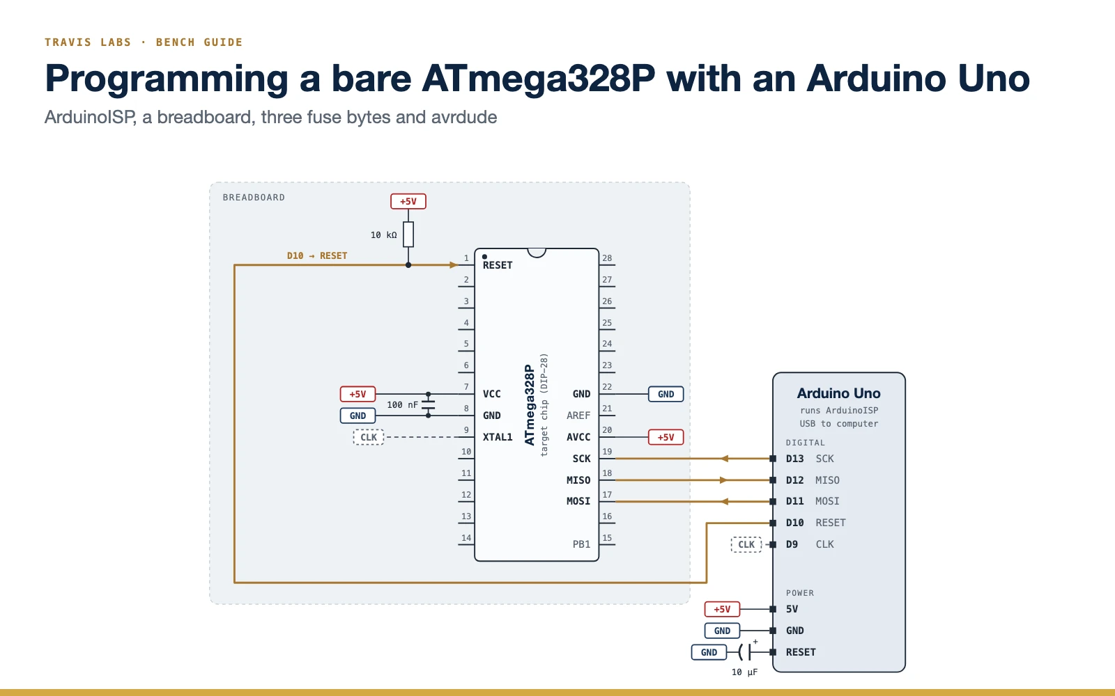
- Hardware In-System Programmer (ICSP) & Bootloader: The ATmega328P comes pre-flashed with a lightweight Optiboot bootloader (occupying just 512 bytes of Flash). When reset, the bootloader listens briefly for incoming hex binaries from the USB interface, eliminating the requirement for dedicated external hardware programmers.
Prerequisites for Learning Embedded Hardware and Firmware
Getting started with embedded systems does not require an advanced physics degree, but grasping foundational engineering concepts will accelerate your trajectory. You should cultivate familiarity with:
- Fundamental Electronics: Understanding Ohm's Law (voltage = current × resistance), Kirchhoff's Voltage and Current Laws, pull-up/pull-down resistor arrangements, and capacitor decoupling.
- Circuit Analysis & Safety: Knowing how to read a schematic diagram, trace current return paths to ground, calculate LED current-limiting resistors, and measure test points using a digital multimeter.
- Core Programming Logic: Mastering basic procedural programming constructs including conditional branching, loops, memory pointers, and variable types.
If you are just getting started with low-level software architecture, reviewing our guide on firmware development basics will give you a clear roadmap for structuring robust, bug-free embedded code.
Setting Up the Toolchain and Writing Embedded Firmware
Embedded programming requires translating human-readable source code into binary machine instructions, followed by writing those bytes directly into the target microcontroller's non-volatile flash memory.
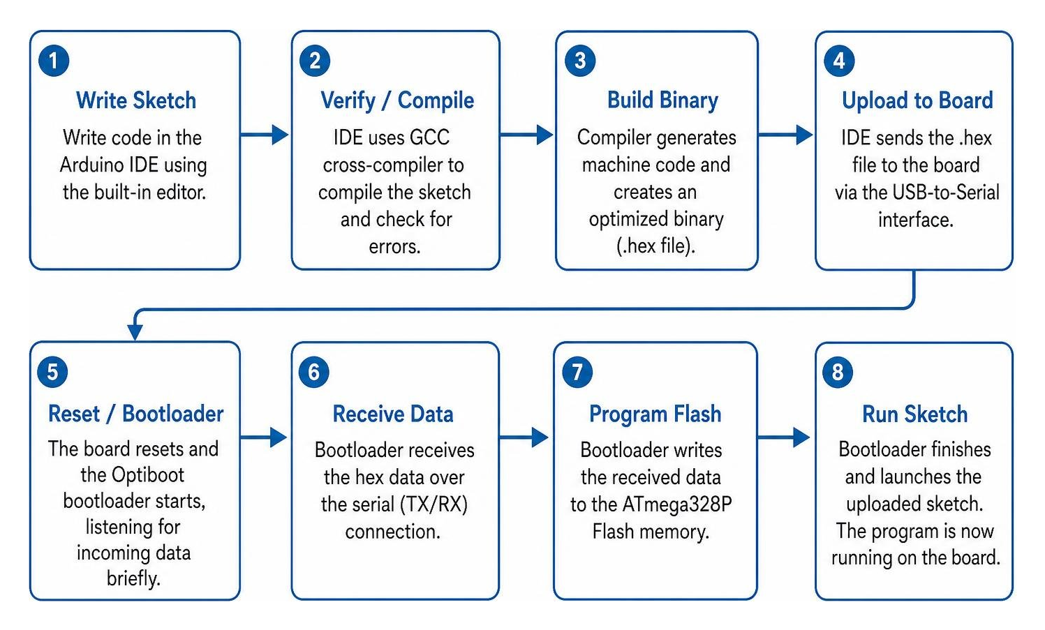
Arduino IDE Setup and Compilation Flow
The Arduino Integrated Development Environment (IDE) manages the underlying GCC cross-compiler toolchain behind a streamlined user interface. Setting up your workstation follows a clean, structured workflow:
- Software Installation: Download and install the latest Arduino IDE for your operating system.
- Hardware Connection: Connect your development board to your workstation using a high-quality, shielded USB cable capable of both power delivery and high-speed data transfer.
- Port and Board Enumeration: Open the IDE, navigate to the Tools > Board menu, select your specific board model, and designate the active virtual communication port from the Tools > Port list. On Linux environments, make sure your user profile belongs to the dialout group to grant unrestricted serial permissions.
- The Compilation Pipeline: When you click Verify, the IDE parses your sketch, resolves imported headers, and invokes the
avr-gccorarm-none-eabi-gcccompiler. The toolchain compiles the C/C++ files, links standard libraries, and emits an executable Intel HEX or binary image. - Flashing the Target: Clicking Upload asserts the Data Terminal Ready (DTR) line to reset the board MCU. The onboard bootloader immediately engages, acknowledges the host flash utility, receives the compiled machine code over serial UART, and programs the binary into flash memory before handing over execution to your program.
For hybrid boards that run modern real-time operating systems such as the STM32U5-powered hardware documented in the Zephyr OS user manual tutorials, the toolchain integrates RTOS compilation rules, letting developers deploy containerized real-time threads across multicore architectures.
Arduino C/C++ Syntax, Control Structures, and Memory Management
Every native sketch relies on two fundamental execution boundaries:
void setup(): Executes exactly once upon system power-up or hardware reset. This block is dedicated to initializing peripheral input/output modes, starting hardware timers, setting baud rates, and initializing communications.void loop(): Executes repeatedly in an infinite cycle for as long as the board remains energized. This block runs your state machines, polls sensor inputs, processes telemetry, and toggles actuator outputs.
Understanding data types and their physical footprint is critical when operating within constrained SRAM environments:
bool: Occupies 1 byte of memory, evaluating totrue(1) orfalse(0).byte/uint8_t: An unsigned 8-bit integer holding values from 0 to 255.int/int16_t: On classic 8-bit AVR boards like the Uno R3, an integer has a 16-bit capacity, storing signed values from -32,768 to 32,767. On 32-bit Arm boards, anintdefaults to 32 bits (-2,147,483,648 to 2,147,483,647).long/int32_t: A signed 32-bit integer capable of spanning -2,147,483,648 to 2,147,483,647.float: A 32-bit single-precision floating-point number. While useful for mathematical conversions, floating-point arithmetic on microcontrollers lacking a hardware Floating Point Unit (FPU) is executed via software emulation, consuming considerable CPU cycles.
A common pitfall for beginning engineers is relying heavily on the blocking delay() function. Calling delay(1000) forces the CPU into a hollow loop, rendering the microcontroller blind to external button presses, incoming serial packets, or safety sensor triggers during that full second. Production firmware utilizes non-blocking timer loops built around millis() or hardware interrupts to maintain real-time responsiveness.
Serial Communication, UART, and Debugging Strategies
Universal Asynchronous Receiver-Transmitter (UART) communication forms the primary diagnostic lifeline between embedded hardware and host debugging terminals.
To initialize hardware UART, define the transmission speed using Serial.begin(baudRate) within your setup() block. Standard baud rates include 9600, 19200, 57600, and 115200 bits per second. Both the microcontroller UART registers and the host terminal (such as the IDE Serial Monitor) must be set to the identical baud rate to ensure framed data bytes are parsed accurately without framing or parity errors.
Using Serial.print() and Serial.println() allows you to inspect variable states, confirm execution branches, and output formatted sensor telemetry. When addressing intermittent communication errors, sensor drift, or line-noise interference, reviewing these practical answers to common firmware and IoT questions will help streamline your bench troubleshooting workflow.
Interfacing Peripherals: Sensors, Actuators, and Displays
Microcontrollers bridge physical phenomena and digital logic. Sensors convert physical forces—such as light, pressure, sound, and temperature—into measurable electrical quantities. Actuators perform the reverse, converting digital instructions into mechanical displacement, optical illumination, acoustic signaling, or thermal energy.
| Pin Type / Function | Typical Hardware Voltage Range | Native Resolution | Primary Arduino API Commands | Typical Peripheral Interfaces |
|---|---|---|---|---|
| Digital Input | 0V (LOW) or 5V (HIGH) | 1-bit binary state | pinMode(pin, INPUT);digitalRead(pin); |
Pushbuttons, limit switches, PIR motion sensors, digital encoders |
| Digital Output | 0V (LOW) or 5V (HIGH) | 1-bit binary state | pinMode(pin, OUTPUT);digitalWrite(pin, HIGH); |
Relays, discrete indicator LEDs, solid-state switches, active buzzers |
| Analog Input | 0V to Reference (default 5V) | 10-bit (0 to 1023 integer steps) | analogRead(pin); |
Potentiometers, LDR voltage dividers, thermistors, current-clamp sensors |
| PWM Output | 0V to 5V pulsed square wave (490 Hz / 980 Hz) | 8-bit (0 to 255 duty cycle steps) | pinMode(pin, OUTPUT);analogWrite(pin, dutyCycle); |
Motor speed controllers, LED dimmers, servo pulse generators, proportional valves |
Digital vs Analog I/O and PWM Signal Control
Configuring a digital pin requires setting its operational state with pinMode(pin, mode). Setting the mode to INPUT_PULLUP engages the internal weak pull-up resistor inside the microcontroller die. This ties the logic line securely to 5 volts when an external switch is open, preventing electromagnetic noise from causing the input pin to float unpredictably between logic states.
Reading continuous physical phenomena requires the analog input pins. When analogRead(A0) is called, the internal ADC samples the voltage on the pin and returns an integer between 0 (corresponding to 0.0 volts) and 1023 (corresponding to 5.0 volts). To compute the actual measured voltage in firmware, multiply the raw ADC integer by the step size:
voltage = (adcValue × 5.0) / 1024.0
Microcontrollers cannot natively output a true, variable analog voltage from their digital pins without an external Digital-to-Analog Converter (DAC). Instead, they use Pulse Width Modulation (PWM). By calling analogWrite(pin, value) on PWM-capable pins (marked with a tilde ~ on the board silkscreen), the microcontroller rapidly switches a 5-volt output between fully ON and fully OFF at fixed frequencies (typically 490 Hz or 980 Hz). The parameter value (0 to 255) dictates the signal duty cycle—the percentage of time the signal remains high during each cycle. A value of 128 yields a 50% duty cycle, delivering an average effective power equivalent to 2.5 volts.
Integrating Environmental and Distance Sensors
Sensor integration represents a substantial portion of embedded development. Two illustrative sensors highlight analog and digital time-domain sampling:
- Light-Dependent Resistor (LDR): An LDR changes its internal semiconductor resistance in response to ambient lux. Because microcontrollers read voltage rather than raw resistance, we place the LDR into a voltage divider circuit with a fixed 10k-ohm resistor. As ambient light levels rise, the LDR resistance drops, shifting the divided voltage delivered to analog pin A0.
- Ultrasonic Distance Sensor (HC-SR04): This digital sensor measures spatial distance using acoustic wave time-of-flight. The microcontroller sends a 10-microsecond high pulse to the sensor's
TRIGpin, prompting it to emit an eight-cycle 40 kHz ultrasonic burst. The sensor then sets itsECHOpin high for the precise duration it takes the acoustic pulse to travel to an obstacle and reflect back. Firmware reads this pulse length usingpulseIn(echoPin, HIGH)and computes distance using the speed of sound: distance in cm = pulse duration in microseconds / 58.
Driving Actuators, Relays, and Liquid Crystal Displays
Microcontroller I/O pins are engineered for low-power signal routing, not direct load driving. A single ATmega328P digital pin can safely source or sink up to 20 to 40 milliamperes. Attempting to power a DC motor, heavy solenoid, or high-draw incandescent lamp directly from an I/O pin will trigger thermal overload and destroy the microcontroller silicon.
To control high-power loads, embedded engineers use intermediate switching devices:
- Optocouplers and Relays: Electrically isolate sensitive microcontroller logic from high-voltage AC mains or inductive surges.
- Bipolar Junction Transistors (BJTs) and N-Channel MOSFETs: Act as electronic switches for low-side DC load switching, driven directly by logic-level gate voltages.
- H-Bridge Motor Drivers (e.g., L298N, DRV8833): Allow bidirectional DC motor speed and direction control by selectively routing polarity through four internal switching transistors.
To display real-time telemetry locally without relying on an attached computer terminal, developers routinely interface alphanumeric Liquid Crystal Displays (LCDs), such as the standard HD44780-compatible 16x2 module. Interfacing via parallel wiring requires up to 6 digital I/O lines.
By integrating a PCF8574 backpack module, the LCD connects using the two-wire Inter-Integrated Circuit (I2C) serial bus—Serial Data (SDA) and Serial Clock (SCL)—reducing pin overhead to just two shared lines.
Real-World Applications and Prototyping Pathways
Prototyping on a bench is only the starting point. The principles learned while blinking LEDs translate directly into architecting enterprise-grade industrial monitoring and automation solutions.
From commercial cold-storage telemetry to automated solar array tracking, embedded microcontrollers form the critical sensing and actuation nodes within the broader architecture of IoT remote monitoring software.
Designing a Scalable Arduino-Based Embedded System for IoT and Industry
When taking a prototype from the bench into industrial infrastructure, processing requirements expand. Modern IoT systems often require asymmetric multiprocessing (AMP)—combining low-power real-time microcontrollers with powerful application processors running embedded Linux.
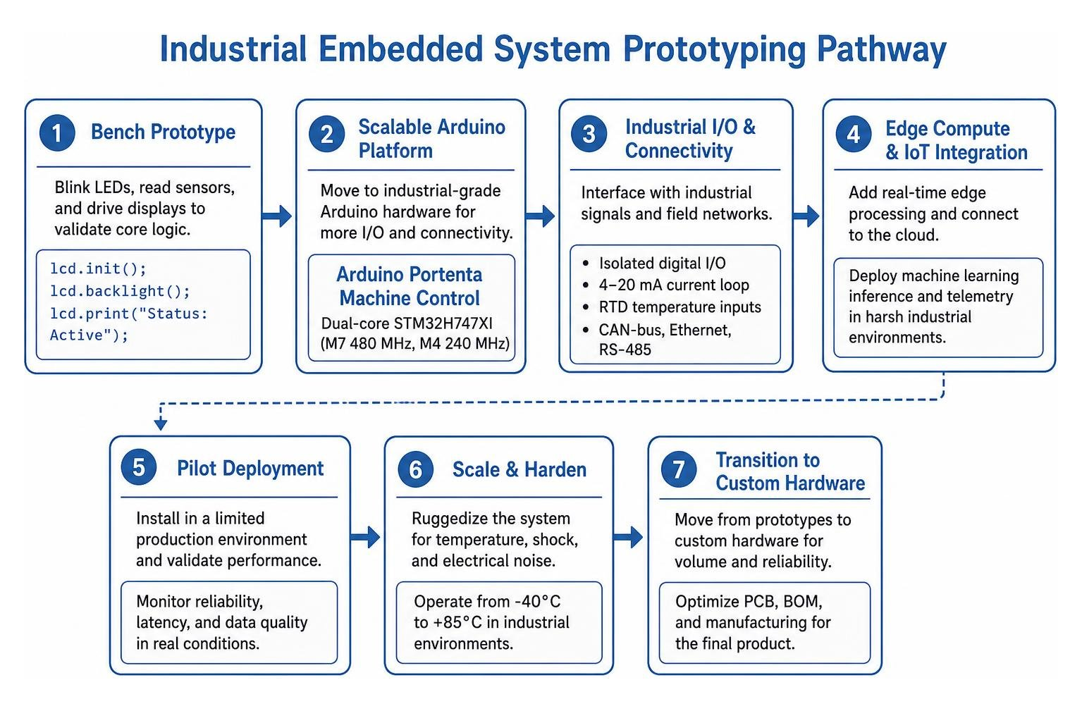
High-performance platforms showcase how far this hardware paradigm has evolved:
- The Arduino Portenta Machine Control: A fully centralized, ruggedized industrial controller driven by a dual-core STM32H747XI processor (Arm Cortex-M7 running at 480 MHz and Cortex-M4 at 240 MHz). It integrates isolated industrial digital I/O, 4–20 mA current loop analog channels, RTD temperature inputs, and integrated CAN-bus, Ethernet, and RS-485 interfaces rated for operation from -40°C to +85°C.
- Industrial Edge Compute: Combining industrial hardware with cloud connectivity allows engineers to deploy real-time edge processing and machine learning inference directly inside harsh factory environments.
Transitioning from Breadboard Prototypes to Custom Hardware
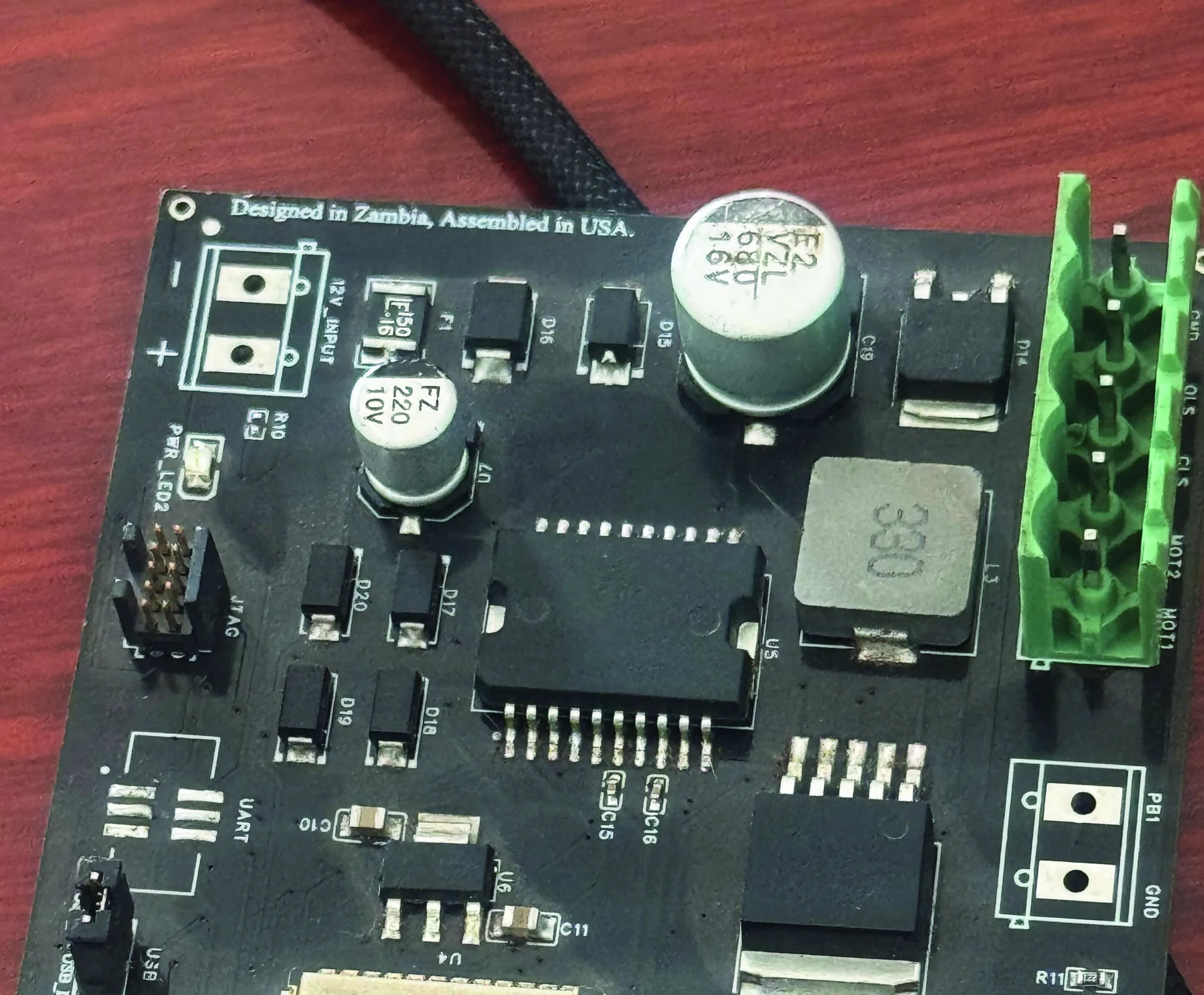
While solderless breadboards and jumper wires are ideal for rapid proof-of-concept testing, they are inherently fragile. Loose jumper contacts, stray parasitic capacitance, and vulnerability to mechanical vibration make breadboards unsuitable for field deployment.
Transitioning a validated breadboard prototype into a rugged, field-deployable product involves a methodical hardware development cycle:
- Schematic Capture: Translate breadboard connections into formal electronic schematics, defining component footprints, decoupling capacitors, transient voltage suppression (TVS) diodes, and power delivery planes.
- Custom PCB Layout: Route copper traces, establish continuous ground planes to minimize electromagnetic interference (EMI), and verify thermal relief for high-current tracks using specialized custom PCB design methodologies.
- Industrial Enclosure Integration: Package the board in an IP65/IP67-rated enclosure with strain-relieved cable glands to protect delicate electronics against moisture, dust, and corrosive industrial atmospheres.
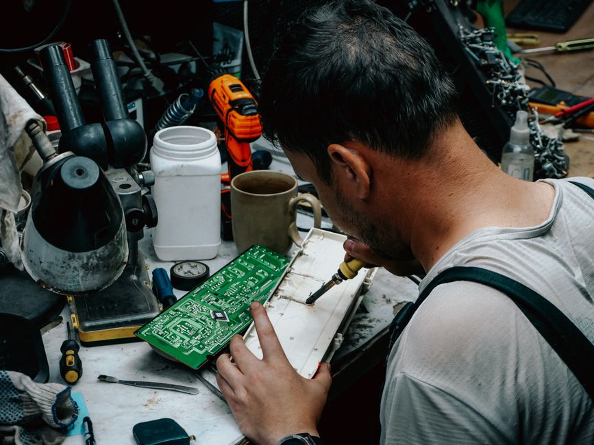
- Hands-on Engineering Training: Mastering this transition requires practical design experience. Aspiring engineers and technical teams can accelerate their hardware skills through structured, hands-on electronics training in Zambia, learning the complete journey from schematic capture to surface-mount soldering.
Frequently Asked Questions About Arduino Embedded Systems
Is Arduino considered a genuine embedded system?
Yes. An Arduino board contains a genuine physical microcontroller running compiled bare-metal machine code that directly controls internal hardware registers, timers, and external I/O peripherals. While its software libraries simplify low-level complexity for beginners, the underlying hardware operates under the exact same deterministic embedded principles used across automotive, industrial, and consumer electronics worldwide.
Which Arduino board is best for beginners in embedded engineering?
The Arduino Uno R3 or Uno R4 Minima remains the benchmark starting point for beginners. Its standard pin layout, robust 5-volt tolerance, easily replaceable components, and vast ecosystem of open-source libraries make it an exceptionally forgiving platform for learning fundamental electronics and firmware development.
How do you transition from Arduino sketches to production-grade firmware?
Transitioning from simple sketches to commercial firmware involves replacing blocking framework abstractions with direct register manipulation, setting up hardware timer interrupts, using DMA (Direct Memory Access) channels, and integrating a Real-Time Operating System (RTOS) like FreeRTOS or Zephyr. Professional developers write modular, MISRA-C-compliant code using professional IDEs such as VS Code with PlatformIO or vendor-specific toolchains (such as STM32CubeIDE or Microchip MPLAB X).
Conclusion
Mastering embedded systems engineering begins with understanding the physical relationship between software logic and real-world hardware. The Arduino platform provides a clear, accessible entry point, demystifying microcontroller registers, input/output peripherals, and hardware communication protocols.
Whether you are building your first automated sensor node on a breadboard or engineering multi-layer industrial controllers for demanding environments, mastering these core principles will give you the foundation needed to design scalable, dependable embedded systems.
For commercial enterprises seeking to turn embedded prototypes into production-grade electronic hardware, our multidisciplinary engineering team at HERO Control Systems delivers end-to-end support across custom electronics, firmware architecture, and rapid prototyping via our dedicated Travis Labs electronics design services.