Demystifying Firmware Development Basics for Aspiring Engineers
Firmware Development Basics: How Hardware Becomes a Working Device
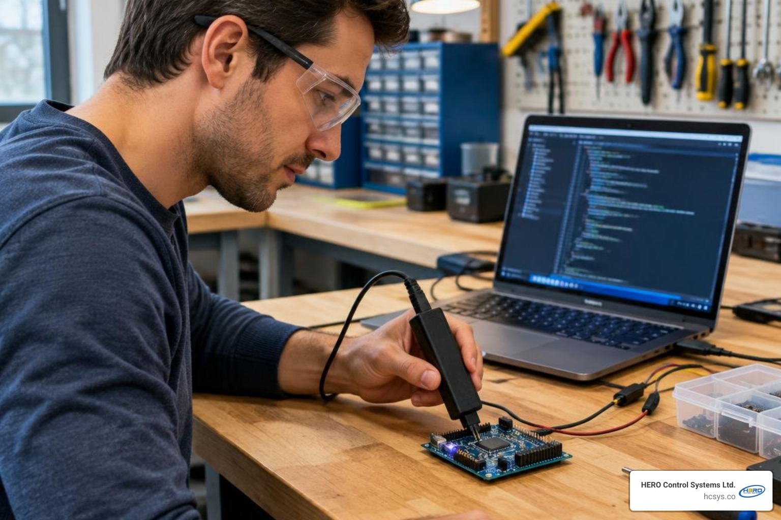
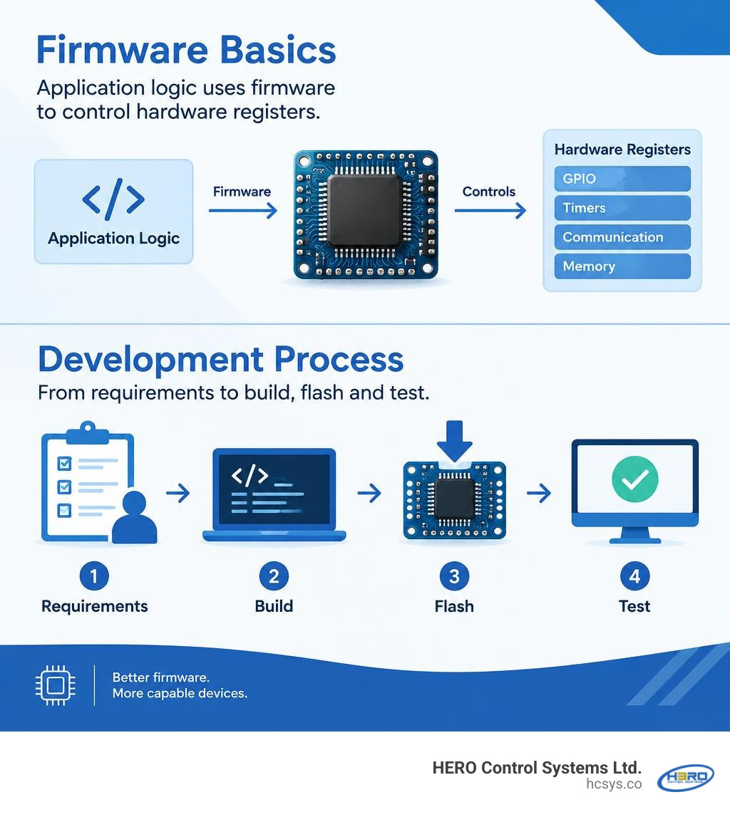
Firmware development basics start with a simple idea: firmware is code that controls a device’s hardware. Unlike most desktop software, it often runs with little memory and must respond to physical inputs on time. To get started, learn the microcontroller’s memory, pins, timers, and communication ports. Then define what the device must do, write and build the code, load it onto the board, and test it on real hardware.
For equipment that must keep running, good firmware also needs clear fault handling, careful testing, and a safe way to update it. This guide explains those choices without assuming you already know how to program a chip.
I’m Eng. Cephas Kalembo, founder and CTO of HERO Control Systems Ltd. My work in PCB design, embedded firmware, and industrial electronics repair shapes this practical guide to firmware development basics.
Core Firmware Development Basics: What Sets Embedded Software Apart
When developing standard PC or web applications, you write software that runs on top of an operating system like Windows, macOS, or Linux. The operating system provides a cozy safety net: virtual memory, automated resource management, and process isolation. If a browser tab crashes, the operating system cleans up the mess and keeps running.
Firmware lives in an entirely different reality. Firmware is software programmed directly into non-volatile memory (such as Flash) on an embedded microcontroller. It operates directly on silicon registers without an intermediary OS layer safeguarding execution. In this realm, your code is directly responsible for configuring physical transistors, managing every byte of system RAM, and meeting strict real-time deadlines.
Microcontrollers (MCUs) are tiny computers on a single chip. While a modern laptop might boast 16 or 32 gigabytes of RAM, a typical 32-bit microcontroller operates with only 32 to 512 kilobytes of Flash memory for storage and 8 to 128 kilobytes of SRAM for runtime execution. Some 8-bit devices function reliably on just 2 kilobytes of RAM. There is no virtual memory swap space; if your stack collides with your heap, the system halts or behaves unpredictably.
Beyond strict resource constraints, embedded software demands deterministic timing. Determinism means that given a specific event or input, the system responds within a guaranteed, mathematically bounded timeframe. In a consumer drone's flight controller or an automotive engine control unit, calculating motor PWM values a few milliseconds too late can cause physical failure. Understanding these physical limits is key to exploring practical embedded firmware fundamentals across real-world hardware.
Hardware Foundations: Understanding the Microcontroller Architecture
To write effective firmware, you must visualize what happens inside the silicon. Microcontrollers like the ubiquitous ARM Cortex-M series integrate a central processing unit (CPU) alongside a collection of dedicated hardware peripherals connected across high-speed internal buses (such as AHB and APB).
- General-Purpose Input/Output (GPIO): Digital pins that read high/low voltage levels or output voltages to drive external circuitry like LEDs, switches, and transistors. They can be configured as floating inputs, pull-up/pull-down inputs, push-pull outputs, or open-drain outputs.
- Hardware Timers: Independent digital counters that tick at clock frequencies. They generate periodic interrupts, calculate pulse widths, measure external signal frequencies, or generate Pulse-Width Modulation (PWM) signals for motor control without loading the CPU.
- The Clock Tree and Phase-Locked Loop (PLL): Microcontrollers do not run on magic; they step through instructions based on clock pulses. Silicon chips use external crystal oscillators combined with internal PLL frequency multipliers to step a low-frequency crystal (e.g., 8 MHz) up to high internal CPU speeds (e.g., 100 MHz to 480 MHz), which is then divided down for specific peripheral buses.
- Nested Vectored Interrupt Controller (NVIC): An interrupt pauses normal code execution immediately when a hardware event occurs (such as a pin changing state or a timer expiring). The NVIC prioritizes these interrupts, executes an Interrupt Service Routine (ISR), and returns the CPU to where it left off.
- Serial Communication Peripherals: Embedded systems rarely work alone. Microcontrollers rely on standard protocols to communicate:
- UART (Universal Asynchronous Receiver-Transmitter): Asynchronous, point-to-point, two-wire (TX/RX) serial data transmission.
- I2C (Inter-Integrated Circuit): Synchronous, multi-device, two-wire (SDA/SCL) bus using pull-up resistors and addressing schemes.
- SPI (Serial Peripheral Interface): Synchronous, high-speed, four-wire bus (MOSI, MISO, SCK, CS) designed for rapid data streaming between chips.
Mastering Firmware Development Basics: The End-to-End Development Lifecycle
Writing firmware requires a dedicated cross-platform engineering workflow. Because microcontrollers do not have monitors, keyboards, or enough storage to run native compilers, developers work on a host computer (PC/Mac/Linux) and produce code targeting the embedded device.
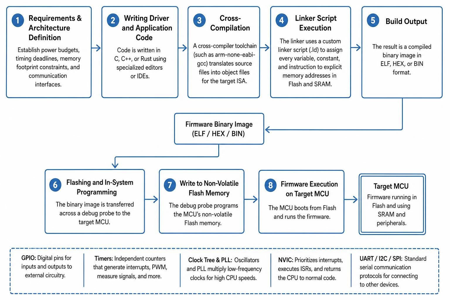
- Requirements & Architecture Definition: Before writing a single line of code, establish power budgets, timing deadlines, memory footprint constraints, and communication interfaces.
- Writing Driver and Application Code: Code is primarily written in C, C++, or Rust using specialized editors or Integrated Development Environments (IDEs).
- Cross-Compilation: A cross-compiler toolchain (such as
arm-none-eabi-gcc) translates your source files into object files specifically structured for the target architecture's Instruction Set Architecture (ISA). - Linker Script Execution: The linker uses a custom linker script (often ending in
.ld) to assign every variable, constant, and instruction to explicit physical memory addresses within Flash memory and SRAM. - Flashing and In-System Programming: The compiled binary image (ELF, HEX, or BIN) is transferred across a debug probe to the target MCU's non-volatile Flash memory.
- Hardware-Level Debugging: The engineer runs, tests, and verifies the firmware against the physical schematic and attached components, often tying directly into custom hardware design integration services to validate board-level electrical integrity.
Selecting an Execution Model: Bare-Metal, RTOS, or Embedded OS
One of the most consequential architectural decisions you will make is choosing how your firmware schedules tasks. Your choice dictates code complexity, responsiveness, memory footprint, and maintainability.
| Metric | Bare-Metal (Super Loop) | Real-Time Operating System (RTOS) | Embedded Linux / OS |
|---|---|---|---|
| Typical Flash Footprint | Extremely Low (< 16 KB) | Low (5 KB – 25 KB kernel overhead) | High (> 16 MB rootfs + kernel) |
| Typical RAM Footprint | Extremely Low (< 2 KB) | Low (1 KB – 10 KB stack allocations) | High (> 32 MB system memory) |
| Interrupt Latency | Direct / Sub-microsecond | Deterministic (1 – 5 microseconds) | Non-deterministic (milliseconds) |
| Scheduling Model | Polling & Interrupt Driven | Preemptive Priority Scheduling | Time-sliced Multitasking |
| Hardware Complexity | Low-cost 8/16/32-bit MCUs | 32-bit MCUs (ARM Cortex-M0+/M4/M7) | High-end MPUs with MMU (Cortex-A) |
| Development Learning Curve | Low | Moderate | High |
Super Loops and Bare-Metal Execution
Bare-metal programming means writing firmware that runs directly on hardware registers without any underlying operating system or scheduler. The foundational structure of bare-metal firmware is the "Super Loop" (an infinite loop often structured as while(1)).
In a basic super loop, the processor executes initialization code once, enters an infinite loop, and sequentially polls flags, reads sensor data, runs state logic, and updates outputs. Time-critical tasks are offloaded to hardware interrupts.
The super loop model offers zero operating system overhead, crystal-clear execution flow, and complete control over silicon behavior. However, as system complexity scales, sequential polling struggles: if Task A takes 50 milliseconds to wait for a slow sensor response, Task C must wait, introducing timing jitter across your system.
Real-Time Operating Systems (RTOS) and Scheduling
When an embedded application must perform multiple complex tasks simultaneously—such as managing an Ethernet stack, scanning user keypad inputs, reading high-speed motor encoders, and driving a graphical display—a Real-Time Operating System (RTOS) is the ideal design choice. Popular open-source RTOS kernels include FreeRTOS and Zephyr.
An RTOS introduces a preemptive scheduler that divides CPU time into slices (commonly 1 millisecond ticks driven by the ARM SysTick timer). Firmware logic is partitioned into independent, concurrent threads called Tasks. Each task receives an assigned priority.
If a low-priority logging task is executing and a high-priority motor control timer elapses, the RTOS kernel triggers a context switch: it saves the low-priority task's register state to its dedicated stack, updates the stack pointer, and immediately executes the high-priority task.
To facilitate safe communication between tasks without memory corruption, RTOS kernels provide synchronization primitives:
- Mutexes (Mutual Exclusion): Binary locks used to protect shared hardware resources (like a single UART port) from concurrent access. Advanced RTOS kernels implement priority inheritance to prevent priority inversion, a hazardous condition where a medium-priority task starves a high-priority task waiting on a low-priority lock.
- Semaphores: Signaling mechanisms used to notify a task that an event has occurred or that a resource count is available.
- Message Queues: Thread-safe, FIFO (First-In, First-Out) memory buffers that allow tasks to pass structured data packets to one another safely.
You can explore these concepts further through this deep-dive developer handbook on RTOS fundamentals to see how scheduling mechanics operate under constrained memory budgets.
Embedded Operating Systems
For systems requiring high-throughput data processing, advanced graphical displays, complex local file systems, or massive networking stacks (such as cellular routers, smart gateways, and industrial HMIs), a full Embedded Operating System like Embedded Linux is necessary.
Unlike microcontrollers, Embedded Linux requires a Microprocessor Unit (MPU) featuring an integrated Memory Management Unit (MMU) and tens or hundreds of megabytes of external DRAM. While Embedded Linux unlocks vast software ecosystems and high-level programming tools, it loses hard real-time determinism; interrupt latencies are subject to kernel process scheduling and non-deterministic memory paging.
Writing Modular Firmware: Drivers, Patterns, and Data Structures
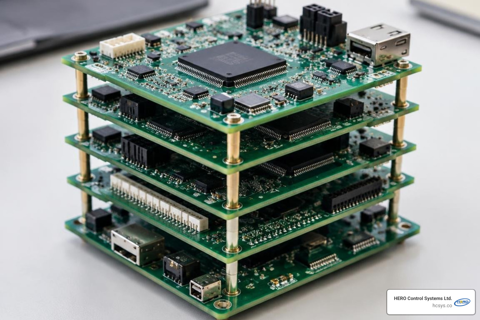
Writing unstructured, spaghetti code directly against microcontroller registers makes software brittle, difficult to debug, and impossible to port to new chips. Professional firmware relies on a layered, modular software architecture.
A standard modular firmware stack features clear separation of concerns:
- Hardware Layer: The physical silicon registers, memory maps, and CPU core.
- Hardware Abstraction Layer (HAL) & Low-Layer (LL) Drivers: Low-level software that manipulates registers directly, exposing clean, functional APIs (such as
UART_WriteByte()orI2C_ReadBuffer()). - Board Support Package (BSP): Code configured specifically for your physical printed circuit board, mapping functional names to designated MCU pins and routing.
- Middleware: Platform-independent libraries, such as RTOS kernels, file systems (FATFS), communication protocols (Modbus, BLE, TCP/IP), and cryptographic suites.
- Application Layer: High-level business logic that governs device behavior, completely abstracted from the underlying silicon vendor.
Essential Design Patterns in Firmware Development Basics
Embedded software engineering benefits heavily from established, lightweight design patterns adapted for hardware constraints:
- Finite State Machines (FSM): Embedded systems are inherently stateful. An automated system (like a battery charger) transitions through distinct states (IDLE, CONSTANTCURRENT, CONSTANTVOLTAGE, FAULT). Implementing state machines via clear
switch-caseconstructs or state transition tables eliminates complex, bug-prone nestedif-elsestatements. - Circular Ring Buffers: When streaming serial data via UART or SPI, data arrives asynchronously. A circular ring buffer uses head and tail pointers within a fixed-size memory array, allowing an interrupt routine to write incoming bytes without dynamic memory allocation while application tasks read processed data at their own pace.
- Publisher-Subscriber (Observer Pattern): Decouples event producers from consumers. When a hardware sensor detects a threshold breach, it broadcasts an event notification to a central dispatcher, allowing multiple subsystems (display, buzzer, telemetry logger) to react without direct coupling to the sensor driver.
- Bitwise Register Manipulation: Hardware control is achieved by toggling individual bits in 32-bit control registers. Mastering bitwise operators (
AND &,OR |,XOR ^,NOT ~, and shift operators<<,>>) is an indispensable baseline skill for any firmware engineer.
Developing Platform-Agnostic Peripheral Drivers
To protect your engineering investments, driver code should never directly mix silicon-specific register addresses with business logic. If a microchip shortage forces your team to swap an STM32 MCU for an NXP or Texas Instruments chip, tightly coupled code requires a complete, expensive rewrite.
By creating abstract driver interfaces, your top-level sensor driver calls generic read/write function pointers. During hardware initialization, you pass the specific platform implementation down to the driver. This clean isolation underpins our work in applied embedded engineering and prototyping, ensuring software assets remain reusable across evolving hardware revisions.
To maximize performance in peripheral drivers, leverage Direct Memory Access (DMA). A DMA controller moves data blocks directly between peripherals (such as an SPI bus or ADC) and SRAM without loading the CPU with byte-by-byte transfer cycles, freeing processor bandwidth for real-time calculations.
Firmware Toolchains, Debugging, and Testing Frameworks
Transforming high-level C/C++ or Rust code into dependable physical execution requires a reliable toolchain, automated build systems, and specialized debugging hardware.
A complete embedded toolchain includes:
- Cross-Compiler: (e.g.,
arm-none-eabi-gcc) Compiles source files into machine code target binaries. - Assembler: Converts low-level assembly startup routines into object code.
- Linker: Resolves symbol references, manages function calls, and maps compiled code sections (
.textfor executable code,.rodatafor constants,.datafor initialized variables,.bssfor uninitialized variables) into hardware memory maps specified by the linker script. - Build Automation Tools: Systems like Makefiles, CMake, or Ninja manage dependency trees and automate cross-compilation with a single terminal command.
- Map File Analyzers: Compiling generates a
.mapfile. Inspecting this file reveals exact byte allocations for every function and global variable, making it invaluable for diagnosing memory exhaustion.
In-Circuit Debugging, Tracing, and Forensics
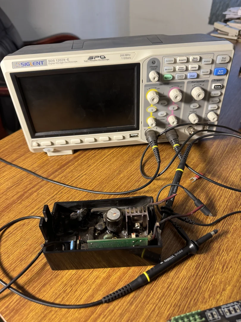
Flashing an LED or printing debug text over UART (printf debugging) is often the first trick engineers learn, but complex real-time bugs require true in-circuit debugging interfaces:
- JTAG (Joint Test Action Group): A standard 4-to-5 wire interface designed for boundary scanning, programming, and hardware debugging.
- SWD (Serial Wire Debug): An ARM-specific, highly efficient two-wire protocol (SWDIO and SWCLK) that provides complete CPU control with minimal physical pin overhead.
Debug probes (such as ST-Link, J-Link, or open-source CMSIS-DAP units running alongside GDB and OpenOCD) allow you to set non-intrusive hardware breakpoints, single-step through assembly instructions, read live register contents, and inspect SRAM values during execution.
ARM Cortex-M cores integrate CoreSight on-chip debug architecture. CoreSight enables real-time instruction tracing (ETM) and variable watchpoints (DWT) without stalling or disturbing the execution timing of the processor.
When firmware encounters catastrophic runtime faults—such as dereferencing a NULL pointer, jumping to an invalid memory address, or executing unaligned memory instructions—the core triggers a HardFault exception. Embedded forensics involves configuring fault handlers to dump the register state (R0-R15, Program Counter, Link Register, CFSR, and HFSR) across a non-volatile log, allowing developers to trace the exact line of disassembly that triggered the crash.
Automated Testing and Host-DUT Test Architectures
Testing firmware solely by hand-clicking buttons on a physical prototype is slow and prone to errors. High-reliability engineering teams integrate automated testing strategies:
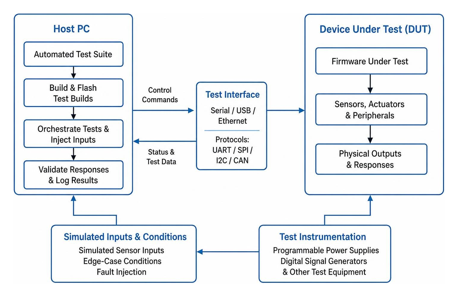
- Host-Based Unit Testing: By mocking hardware abstraction interfaces, substantial portions of business logic, state machines, and mathematical algorithms can be compiled and verified natively on your development PC using unit-test frameworks (such as Unity or CppUTest) inside continuous integration (CI) pipelines.
- Hardware-in-the-Loop (HIL) & Host-DUT Testing: A Host PC orchestrates automated test suites by communicating with a Device Under Test (DUT). The host automatically flashes test builds, injects simulated sensor inputs using programmable power supplies and digital signal generators, asserts edge-case conditions, and validates physical output responses.
Investing early in automated validation and embedded firmware diagnostics and troubleshooting ensures software regressions are caught long before boards are deployed into field operations.
Securing Embedded Devices and Future-Proofing Firmware
As embedded systems connect across industrial networks, commercial facilities, and the Internet of Things (IoT), firmware security is no longer an optional feature—it is a core engineering requirement. Compromised firmware exposes physical infrastructure to remote manipulation, data theft, and catastrophic operational downtime.
The first step in securing embedded systems is managing memory safety risks. Memory corruption bugs, such as stack buffer overflows, remain among the most exploited vulnerabilities in embedded C/C++ development. Writing beyond array bounds allows malicious actors to overwrite return addresses on the stack and redirect CPU execution to injected code. For safety-critical designs, modern teams increasingly evaluate Rust for embedded firmware, leveraging its compile-time borrow checker to guarantee memory safety and eliminate data races without runtime performance penalties.
Hardware-Rooted Trust and Secure Boot
To protect physical hardware against malicious or unauthorized firmware modifications, modern microcontrollers leverage a hardware Root of Trust (RoT).
- Secure Boot: The microcontroller contains an immutable bootloader etched into protected internal ROM. On system power-up, this hardware bootloader reads the application binary in Flash, computes its cryptographic hash (e.g., SHA-256), and validates the calculated hash against a digital cryptographic signature (e.g., ECDSA) using a public key securely stored in hardware fuses. If the signature is invalid or altered, the MCU halts execution immediately.
- Dual-Bank Bootloaders & OTA Updates: Reliable devices in the field must support Over-The-Air (OTA) updates. Robust architectures use dual-bank Flash memory. New firmware is downloaded into Bank B while the system continues running safely from Bank A. Once the download is cryptographically verified, the bootloader toggles the active boot bank. If the new image fails its initial health check, the bootloader automatically rolls back to Bank A, preventing field devices from becoming permanently unresponsive ("bricked").
- Flash Protection and Encryption: Microcontrollers provide read-out protection (RDP) registers. Enabling RDP locks debug access over SWD/JTAG, preventing malicious actors from physically attaching a probe to extract proprietary intellectual property or cryptographic keys.
Frequently Asked Questions About Firmware Development
What programming languages are best for firmware development?
C remains the undisputed industry standard for embedded firmware. It provides direct, deterministic hardware register access, maps cleanly to assembly instructions, and has mature cross-compiler support across every microcontroller architecture.
C++ is widely used in modern firmware when developers leverage object-oriented abstractions, templates, and RAII (Resource Acquisition Is Initialization) without utilizing heavy runtime overheads like dynamic memory allocation (new/delete) or exceptions.
Rust is rapidly gaining adoption in safety-critical, industrial, and connected embedded systems. Rust provides native memory safety, strong typing, and concurrency guarantees without the overhead of a garbage collector, catching memory corruption bugs at compile time.
Assembly language is rarely used to write entire applications today. Instead, it is reserved for fine-tuning performance-critical math routines, context-switching routines in RTOS kernels, and low-level CPU startup code.
What is the difference between a microcontroller (MCU) and a microprocessor (MPU)?
A microcontroller (MCU) integrates the CPU core, non-volatile Flash memory, SRAM, and peripheral interfaces (GPIO, UART, Timers) onto a single silicon chip. MCUs are designed for low power consumption, real-time deterministic control, and bare-metal or RTOS execution environments.
A microprocessor (MPU) contains only the high-speed processor core (and cache memory) on the chip. It relies on external memory chips (DDR RAM, eMMC/NAND Flash) and peripheral controllers routed across the circuit board. MPUs include a Memory Management Unit (MMU) capable of running complex, multi-user operating systems like Embedded Linux, but they consume significantly more electrical power and exhibit non-deterministic timing.
How do you prevent and troubleshoot HardFault errors in ARM Cortex-M?
HardFault exceptions occur when the CPU core detects an unrecoverable hardware or software execution error. Common root causes include:
- Stack Overflow: A task exceeds its allocated stack space, silently corrupting neighboring RAM variables.
- NULL Pointer Dereference: Attempting to read or write data to address
0x00000000. - Unaligned Memory Access: Attempting to read a 32-bit word from an unaligned memory boundary without hardware support.
- Accessing Disabled Peripherals: Attempting to modify peripheral registers before enabling the peripheral's clock source in the system clock control register (RCC).
To troubleshoot a HardFault, configure a custom assembly fault handler that reads the stack frame at the moment of the crash. Inspect the Program Counter (PC) to locate the exact instruction that triggered the fault, and review the Configurable Fault Status Register (CFSR) and HardFault Status Register (HFSR) inside your debugger to determine the specific hardware violation.
Conclusion
Mastering firmware development basics bridges the divide between abstract software logic and real-world physical machines. Building reliable embedded systems requires a solid understanding of microcontroller architectures, clean execution scheduling, platform-agnostic driver designs, in-circuit debugging techniques, and robust security practices.
Whether you are configuring a bare-metal super loop for an ultra-low-power environmental sensor or deploying an RTOS-driven multi-tasking controller for high-reliability industrial automation, the engineering fundamentals remain the same: design for constraints, enforce determinism, and validate continuously on physical hardware.
At HERO Control Systems Ltd., we turn complex engineering concepts into dependable physical products. From our integrated engineering labs in Lusaka, Zambia, our team provides complete, end-to-end design, manufacturing, and development capabilities. Whether you are building next-generation hardware prototypes, optimizing existing firmware architectures, or seeking specialized industrial electronics support, connect with our team for professional electronics and embedded firmware development services tailored to your mission-critical applications.