DC regulated vs adjustable power supply: what's the difference?
"Regulated" and "adjustable" are not two kinds of power supply. They answer two different questions. Regulated means the supply holds its output steady when the load or the mains changes. Adjustable means you can set what that output is. Most bench supplies are both, whatever the front panel calls them.
Two supplies on our Lusaka bench show this well. One is labelled "DC regulated power supply", the other "Adjustable DC power supply". Both are regulated, and both are adjustable. What really separates them is range, power and how they are built. This article explains each term and what the knobs do. It also shows how to wire a dual supply, how to work safely at high voltage, and what to check before you buy a supply in Zambia.
Regulated: does the output stay put?
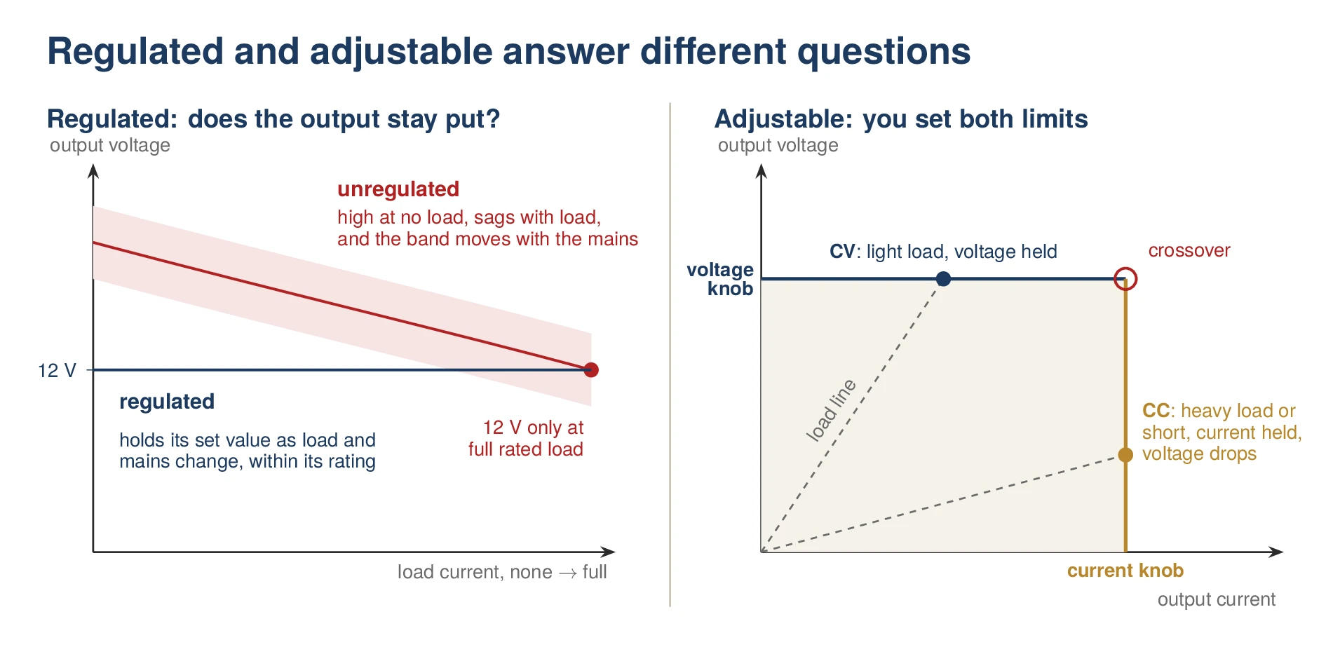
Every DC supply turns mains AC into DC. The simplest way is a transformer, a bridge rectifier and a capacitor. That is an unregulated supply, and its output moves with everything around it:
- With the load. A "12 V" unregulated adapter usually gives 12 V only at its full rated current. With a light load it often reads well above 12 V.
- With the mains. The output rises and falls in step with the incoming voltage. ZESCO's nominal supply is 230 V, but the voltage at a socket can stray from that, especially at the end of long lines and when power returns after load-shedding.
- With ripple. On 50 Hz mains the capacitor is recharged 100 times a second, so the output carries a sawtooth ripple that grows with the load.
A regulated supply measures its own output and corrects it all the time. Its output stays at its set value as the load and the mains change, within its rating. Three numbers on a datasheet tell you how well it does that:
- Load regulation: how far the output moves between no load and full load.
- Line regulation: how far it moves when the mains input changes across its range.
- Ripple and noise: the AC left riding on the DC, in millivolts rms or peak to peak.
Regulated does not mean adjustable. A phone charger, a 12 V CCTV power supply, a 24 V DIN-rail supply in a control panel and a −48 V telecom rectifier are all regulated, and each is meant to sit at one voltage. The rectifier's output moves only within a narrow band, set by the site controller for float and boost charging of the batteries.
Adjustable: you set the limits
An adjustable supply lets you choose the output. On a proper bench supply you set two things, not one:
- The voltage knob sets the highest voltage the supply will give.
- The current knob sets the most current it will let flow.
The load decides which limit it reaches first. With a light load the supply runs in constant voltage (CV): the voltage holds at your setting and the load draws whatever current it needs. When the load tries to draw more than your current setting, because of a fault, a short or a flat battery, the supply moves to constant current (CC). The current then holds at your setting, and the voltage falls as far as it must. The point where it changes over is called the crossover.
Many supplies have CV and CC lamps. On one without them, watch the voltmeter: if the voltage sits below your setting, the supply is in CC.
The current knob is the most useful control on the bench. Set low, it turns a short circuit on a repaired board into the small current you chose and a falling voltmeter, instead of smoke. CC mode is also how a battery charger works: constant current until the battery reaches its voltage, then constant voltage while the current tapers off.
Four combinations
| Fixed output | Adjustable output | |
|---|---|---|
| Unregulated | Old transformer adapters; simple battery chargers | Many old "3–12 V" selector adapters, which only switch transformer taps |
| Regulated | Phone chargers, 12 V CCTV supplies, 24 V DIN-rail supplies, −48 V telecom rectifiers | Bench supplies, including both of ours |
When someone asks for "a DC regulated supply" for a workshop, they usually mean the bottom-right box: a regulated, adjustable bench supply.
The two supplies on our bench
DF1731SL10A: "DC regulated power supply"
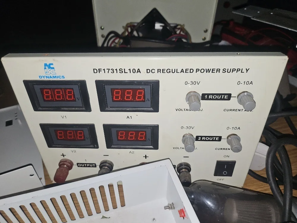
The supply in the photo at the top of this article is a dual bench supply. It has two channels, each 0–30 V and 0–10 A, each with its own voltage and current knobs and its own voltmeter and ammeter. The panel calls the channels "1 ROUTE" and "2 ROUTE". That is a literal translation of the Chinese 路 (lù), which many imported instruments use to count channels. Read "route" as "channel".
Two things to know about a supply like this:
- The meters are for setting, not measuring. Three-digit displays are fine for setting a voltage. But at high current the board sees less than the meter shows, because the leads drop voltage too. When it matters, measure at the board with a multimeter.
- Each channel can deliver up to 300 W. At 10 A, use thick, short leads, tightened under the binding posts with ring lugs or bare wire. Crocodile clips get hot.
IPS-ATD70010: "Adjustable DC power supply"
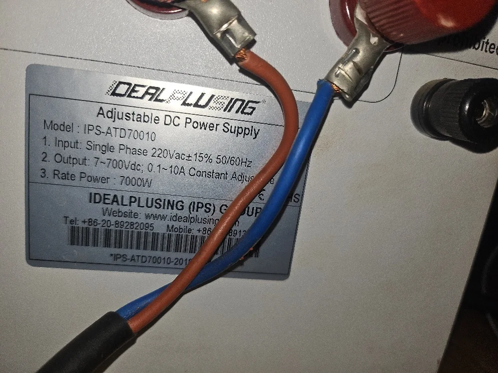
The second supply's rating plate reads: single-phase 220 V AC ±15%, 50/60 Hz in; 7–700 V DC and 0.1–10 A out, both adjustable; 7,000 W rated power. It is also a CV/CC supply, so it is just as regulated as the first one. It is simply built for a different job.
- It starts at 7 V. It cannot give the 3.3 V or 5 V that logic boards need, and its smallest current setting is 0.1 A. It is the wrong supply for the first power-up of a small board.
- It reaches 700 V. That covers the high-voltage side of power electronics, jobs a 30 V supply cannot do. They are listed below.
- It is almost certainly a switching design. At 7 kW, a linear supply would turn most of its power into heat at low output voltages.
Linear or switching: the difference that matters
Behind the labels, the real split between bench supplies is how they regulate.
- Linear supplies use a mains transformer, a rectifier and a power transistor that drops the difference between the internal DC and your setting. They are electrically very quiet, often around a millivolt of ripple, and they recover quickly when the load changes. But they are heavy and they run hot. If the internal DC is about 35 V, delivering 5 V at 10 A leaves the transistor about 300 W to get rid of. Better designs switch transformer taps to cut this. Dual 30 V bench supplies in the DF1731 style are commonly linear; a heavy case and a large mains transformer inside are the giveaways.
- Switching supplies chop the DC at tens or hundreds of kilohertz and use a small high-frequency transformer. They are light and efficient, and they are the only practical way to reach kilowatts. The cost is more noise on the output, typically tens of millivolts peak to peak, and electrical noise sent back into the mains.
For audio, radio, sensor and precision analogue work, a linear supply is the safer choice. For power electronics, battery work and anything above a few hundred watts, a switching supply is the practical one.
First power-up of a repaired board: use the current knob
- Set the current limit before you connect anything. Short the output leads together, turn the current knob until the ammeter shows your limit, then remove the short. Start low: a little above the board's expected current, or a low value such as 100 mA for a small control board if you do not know it.
- Set the voltage with the leads apart, using the voltmeter, then switch the output or the supply off.
- Check the polarity twice, then connect. Many boards have no reverse-polarity protection.
- Switch on and watch both meters. If the voltage holds and the current settles below the limit, the board is drawing normally. If the voltage collapses and the current sits on the limit, the supply is in CC: there is a short or a heavy fault. Switch off.
- Find a short with the limit, not with fire. With the current held at a safe value, the faulty part is often the one that warms first. Find it with a thermal camera, or with a careful fingertip on a low-voltage board.
- Raise the limit in steps once the board behaves, up to its normal working current.
Two channels: independent, in series, or as a split supply
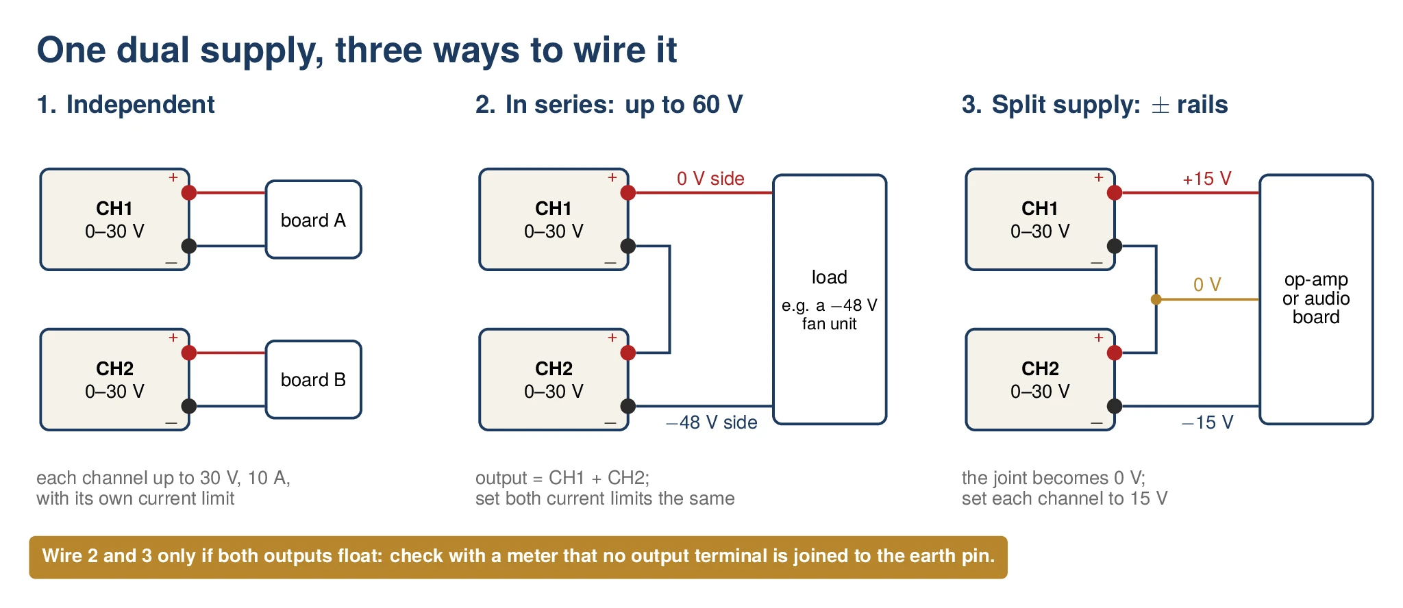
- Independent. Two separate supplies in one box, for example 12 V for a control board and 5 V for its display.
- In series, for up to 60 V. Join CH1's negative to CH2's positive, and take the output across CH1's positive and CH2's negative. With each channel at 24 V you have 48 V, enough to bench-test −48 V telecom equipment such as a BTS fan unit. On −48 V equipment, the 0 V terminal (often marked RTN or GND) goes to the top positive, and the −48 V terminal to the bottom negative. Set both current limits to the same value.
- As a split supply. Join the channels the same way, but use the joint as 0 V. CH1's positive becomes +15 V and CH2's negative −15 V, the ± rails that op-amp, audio and many sensor boards need.
Series and split wiring work only if the outputs float, meaning no output terminal is connected to the mains earth. Most bench supplies are built that way, but check yours. With the supply unplugged, measure the resistance from each output terminal to the earth pin of its plug: it should read open. If a channel is earthed, joining the two channels can short one of them through the earth.
Working safely at 700 V
A supply like the IPS-ATD70010 brings a different level of risk. Anything above 120 V DC is beyond extra-low voltage, and 700 V DC can kill.
- Switch the output off before you connect or disconnect. DC has no zero crossing to put out an arc, so a lead pulled off under load at hundreds of volts can draw a sustained arc.
- Use leads, clips, probes and meters rated for the voltage, 1,000 V or more, and fit crimped lugs on the output terminals, as in the photo.
- Treat capacitors as live. The supply's output capacitors and the load's own capacitors, such as a drive's DC bus, can hold a lethal charge after switch-off. Measure before you touch.
- Start with the current limit low, exactly as with a small board. At 700 V, the current limit is what stands between a failed part and a violent failure.
- Never work on high voltage alone. Keep the bench clear of loose metal, and keep one hand away from the work where you can.
What a high-voltage supply is for
- Testing a drive's power stage from DC. The DC bus of a 400 V variable-speed drive sits at about 540–565 V, and many drives have DC bus terminals. After a repair, a current-limited DC supply on those terminals brings the bus up gently and in steps. A shorted IGBT then shows up as a supply sitting in current limit, not as a blown module.
- Testing the PV inputs of solar inverters. Load-shedding has put hybrid solar inverters in homes and businesses across Zambia, and their PV inputs run at hundreds of volts. A CV/CC supply set inside the inverter's MPPT range can check that the input stage powers up and converts. It is not a true solar-array simulator, because it does not follow a panel's curve, so some trackers will hunt.
- The high-voltage stages of rectifiers and power supplies. In a telecom rectifier, the PFC stage feeds a DC link of around 400 V to the DC/DC stage. In many designs, feeding that link from a current-limited supply lets you test the DC/DC stage on its own.
- High-voltage battery electronics. Bench tests on the DC/DC converters and protection circuits of storage and EV battery packs need a supply in their voltage range. See our article on why battery electronics fail before the cells.
Plan the mains supply for it
The plate says 7,000 W out. Assuming about 90% efficiency and a power factor near 1, neither of which the plate states, that is roughly 7.8 kW in. That means about 34 A at 230 V, and over 40 A if the mains sags to the bottom of the supply's 187–253 V input range. An ordinary 13 A socket gives about 3 kW, so on a socket the supply must run far below its rating. Full power needs a dedicated circuit, sized and installed by a qualified electrician. If you run it from a generator during load-shedding, size the generator for the input power, not the output.
Buying a bench supply in Zambia: what to check
- CV and CC on every channel, with a current limit you can set, not just a fuse.
- An output on/off switch, so you can set both limits before the board is connected.
- Load regulation, line regulation and ripple figures on the datasheet. A supply sold without them is an unknown.
- Linear or switching, chosen for your work, as above.
- Floating outputs, if you plan to wire channels in series or as a split supply.
- An input range that covers 230 V with room for sags and surges.
- Over-voltage protection (OVP), so a fault or a knob turned by mistake cannot push the output past a safe limit.
- A fan you can reach. Bench supplies pull dust through their heatsinks like any other electronics in Zambia's dry season, so clean them.
- Proper binding posts that take banana plugs, ring lugs and bare wire.
- Repairability: standard parts, and someone who can fix it locally.
We repair power electronics in Lusaka, from telecom rectifiers to drives and inverters. See our industrial repair service, or contact us.