How we repair ZTE telecom rectifiers, and what fails most
Every mobile site in Zambia runs on −48 volts DC. The radios, the baseband units and the transmission equipment all draw from one DC bus, and the site batteries float on that same bus. Rectifier modules make it from the grid or the generator. Several modules share the load in a power shelf, so one failure rarely takes a site down on its own. But each failed module leaves less margin. At a site already cycling through load-shedding, that margin is what recharges the batteries before the next outage.
This article opens a ZTE rectifier on our Lusaka bench. It explains how the module works, what fails most and why, and how we repair and test one. It is written for site engineers, power technicians and anyone deciding whether a dead module is scrap.
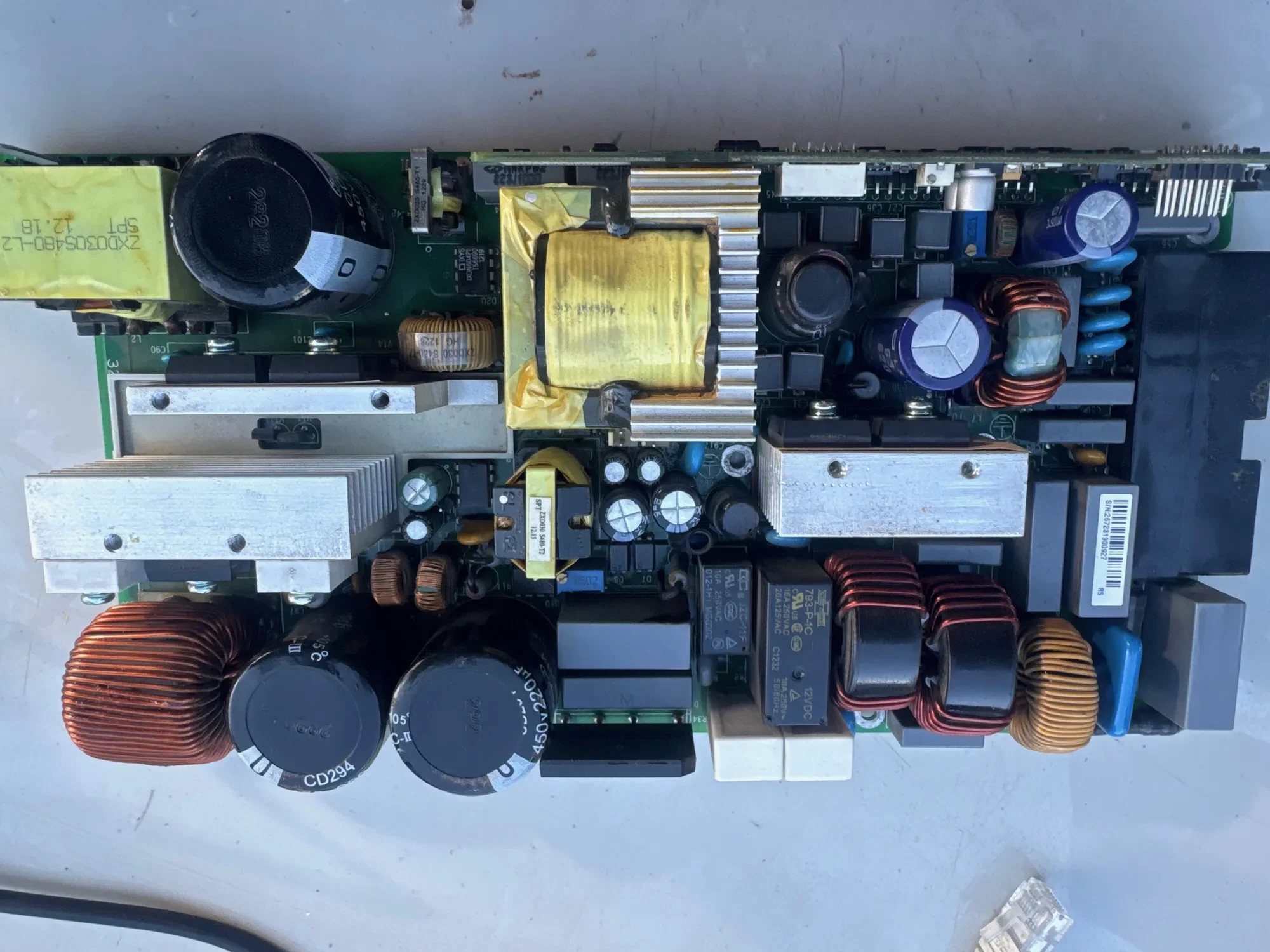
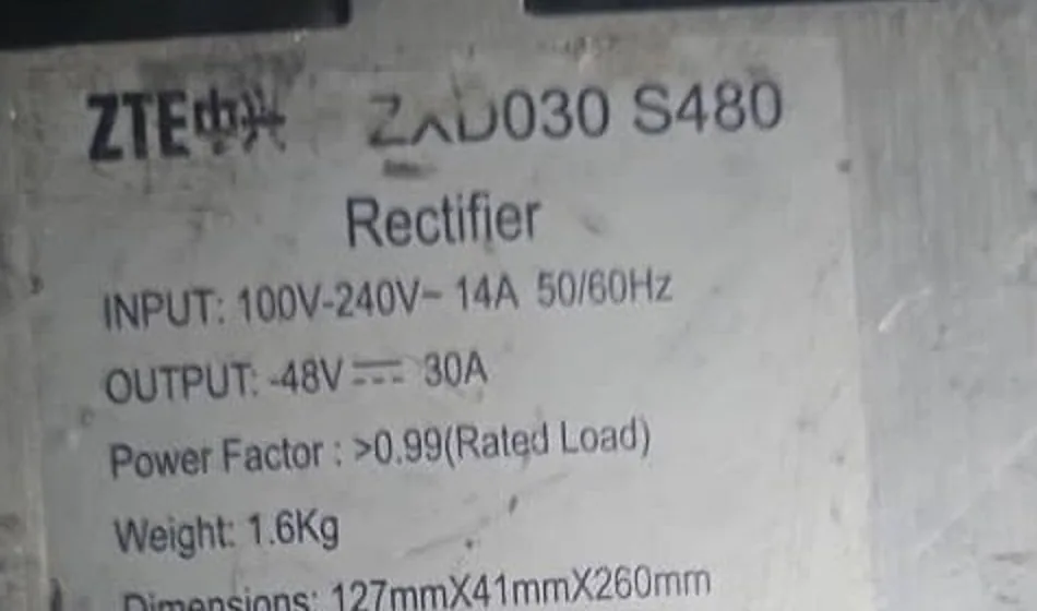
The module on our bench: ZTE ZXD030 S480
The ZXD030 S480 is a plug-in rectifier module. Its nameplate gives an input of 100–240 V AC and an output of −48 V DC at 30 A, so roughly 1.5 kW per module. It slides into a ZTE power shelf beside other modules and a controller. The controller sets the output voltage, manages battery charging and reports alarms to the network operations centre. ZTE's range also includes larger modules, such as the 50 A ZXD2400 family used in ZXDU58 power systems. The repair approach below applies to all of them.
What is inside a telecom rectifier
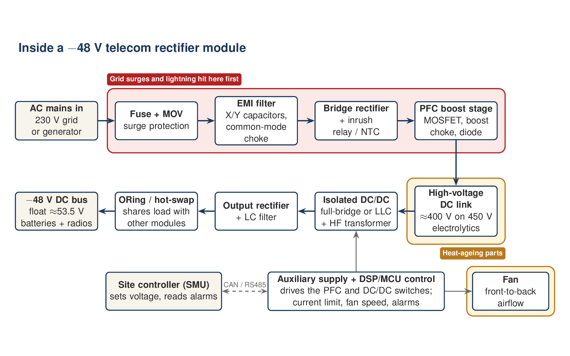
Every modern telecom rectifier, ZTE, Huawei or any other make, follows the same chain. Knowing the chain is what makes component-level repair possible.
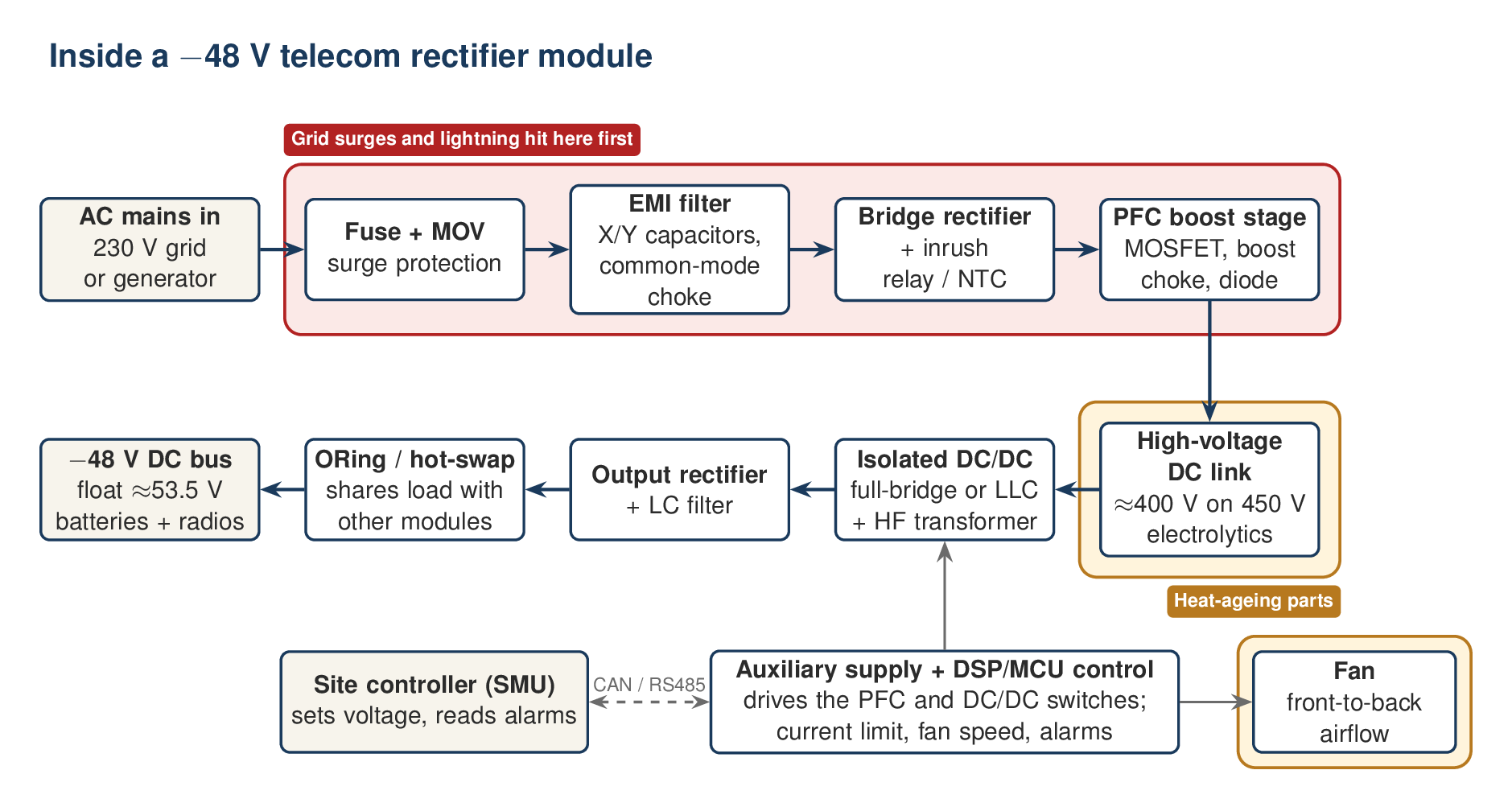
- Input protection. A fuse and one or more metal-oxide varistors (MOVs) clamp surges from the mains.
- EMI filter. X and Y capacitors and common-mode chokes keep the module's switching noise out of the grid, and the grid's spikes out of the module.
- Bridge rectifier and inrush limiting. The bridge turns AC into pulsating DC. A relay, often with an NTC thermistor, limits the surge of current into the capacitors at switch-on.
- Power factor correction (PFC). A boost converter (a MOSFET, a large choke and a fast diode) draws current in step with the mains voltage and lifts the DC to around 400 V.
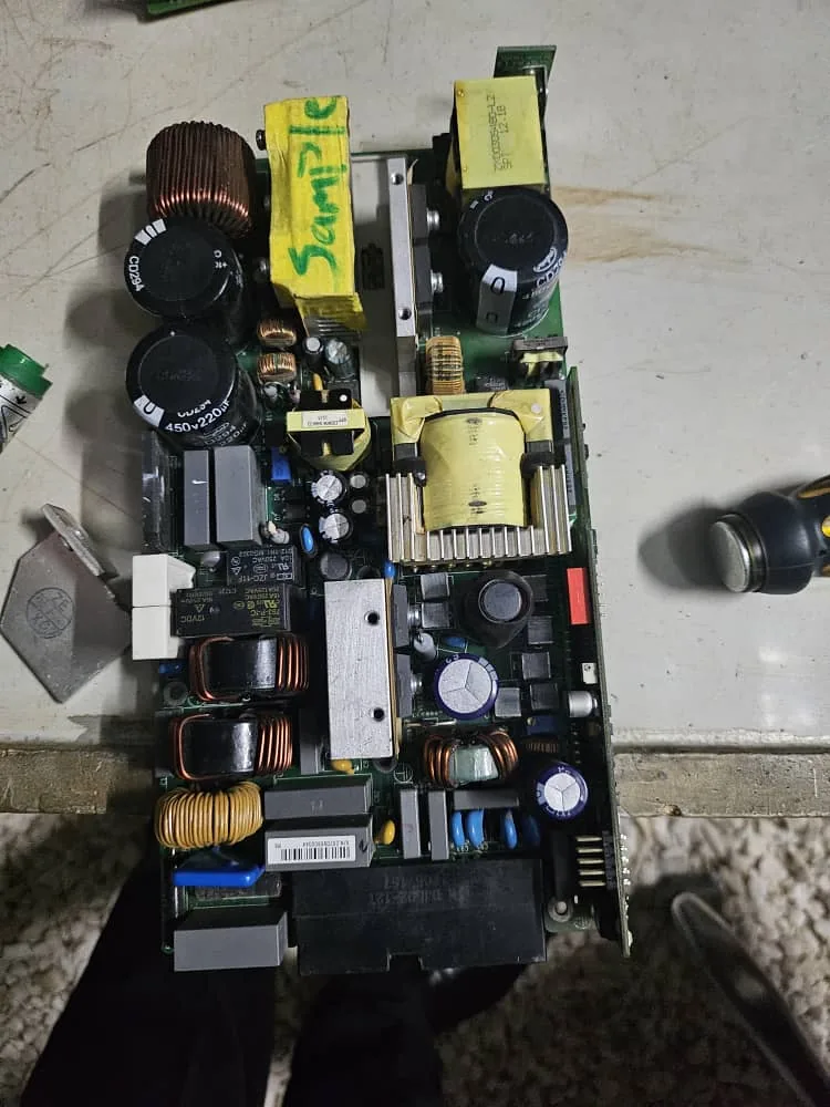
- The DC link. Large electrolytic capacitors store that 400 V. On the ZXD030 board there are two 450 V, 220 µF capacitors.
- Isolated DC/DC converter. A full-bridge or resonant (LLC) converter chops the 400 V at high frequency through a transformer, which also provides the safety isolation.
- Output rectification and ORing. Rectifiers and a filter make clean DC. An ORing stage lets the module share the bus with its neighbours and isolates it if it fails.
- Control, auxiliary supply and fan. A small auxiliary supply powers the control chip, which runs both power stages, limits current, drives the fan and talks to the shelf controller.
What fails most, and why
1. The grid side: input protection, EMI filter and PFC
We recently restored two rectifiers from Zambian tower sites, one ZTE ZXD030 S480 and one Huawei R4875G1. Both had failed in exactly the same place. The EMI filter and input protection were blown, and the PFC stage had been taken out behind them. Two units are not a statistic. But the pattern has a clear cause: grid-side stress, not old age.
A MOV is sacrificial. It absorbs surges until one is larger than it can take, and then the energy goes further in, through the bridge and into the PFC MOSFET. When that MOSFET fails short, it usually takes a chain of parts with it: its gate resistor, the gate driver, the current-sense resistor and the fuse. A repair that replaces only the MOSFET fails again at the first switch-on.
Zambian sites see more of this stress than most. During load-shedding a site may move between grid, generator and batteries several times a day, and every changeover is a transient. The rainy season, roughly November to April, brings lightning that couples into long rural lines. Generators that hunt or over-speed add their own voltage swings.
2. Electrolytic capacitors
Electrolytic capacitors dry out with heat. A widely used rule of thumb is that their life roughly halves for every 10 °C rise in temperature. The DC-link capacitors and the small capacitors in the auxiliary supply are the usual victims. Typical symptoms are a module that will not start, restarts under load, or shows high ripple on the output.
3. The auxiliary supply
If the small supply that powers the control chip dies, the whole module looks dead. There are no LEDs and no output, even though the main power stages may be perfectly sound. This is one of the most satisfying repairs, because the parts involved are cheap.
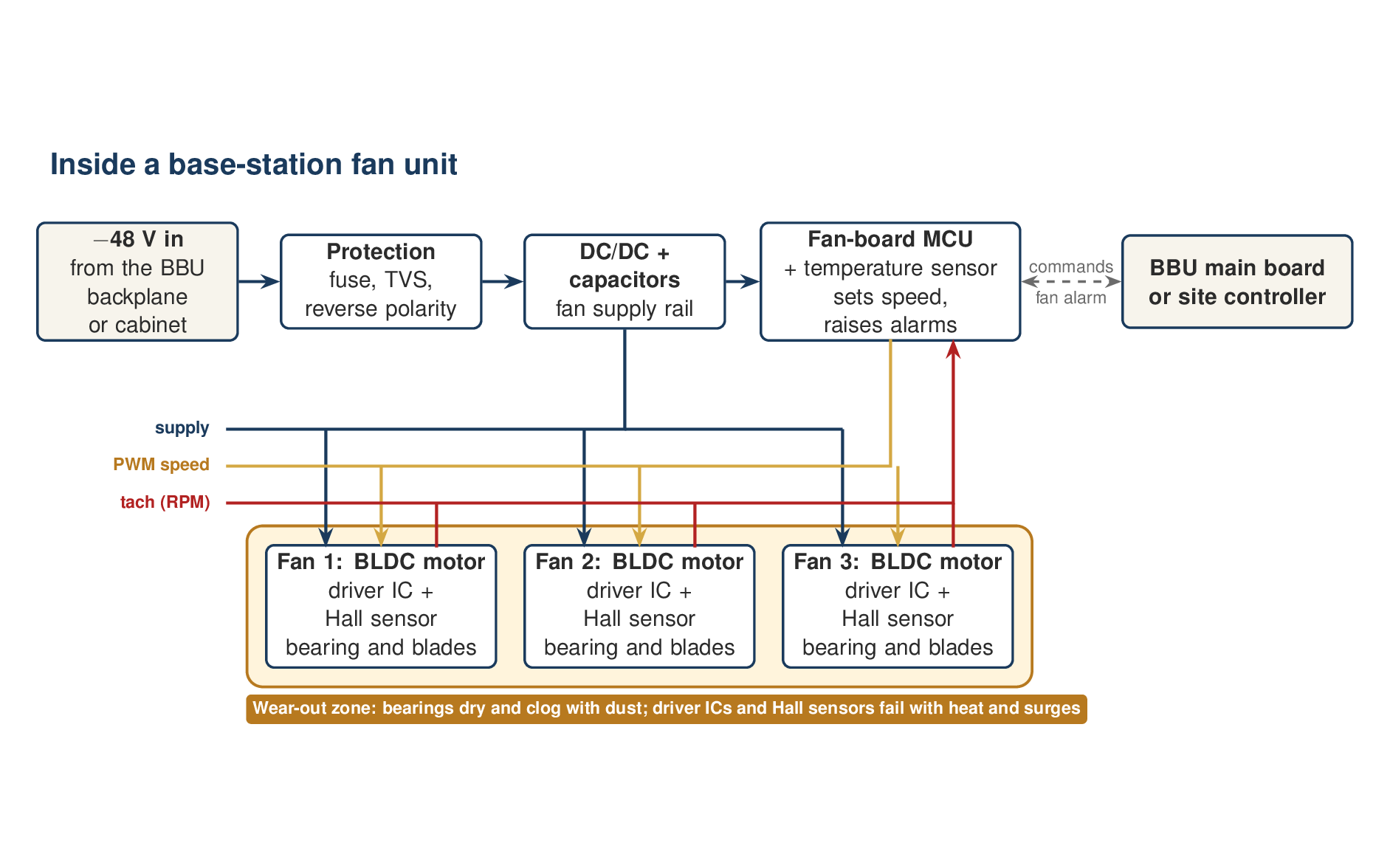
4. Fans
Rectifier modules are densely packed and depend on their fans. Dust from Zambia's dry season clogs filters and wears bearings. A slow fan makes the module derate its output or shut down on over-temperature.
5. Inrush relay and output stage
Relay contacts burn or weld after repeated switching into charged capacitors. Output-side faults in the rectifiers, ORing devices and filter capacitors are less common, and are often a consequence of a fault elsewhere.
How we repair a ZTE rectifier, step by step
- Intake. Record the serial number, nameplate, site and symptom, along with the controller's alarm history if the operator can export it. Photograph the module before opening it.
- Make it safe. The DC-link capacitors can hold around 400 V long after the module is unplugged. Measure them, and discharge them through a suitable power resistor. Never short them with a screwdriver.
- Look and smell. Under magnification, look for a cracked or blackened MOV, a blown fuse, carbon tracking, scorched resistors near the PFC MOSFET and bulging capacitors.
- Cold tests. With the module unpowered, use diode mode and resistance to check the bridge, the PFC MOSFET and diode, the primary-side MOSFETs and the output rectifiers. Check every gate resistor and current-sense resistor, and measure capacitor ESR. Find the whole chain of damage, not just the first failed part.
- Replace with the right parts. Use equal or better ratings for voltage, current and switching characteristics, in the same package and with the same thermal path. Counterfeit power MOSFETs are a real risk, so buy from authorised distributors.
- Controlled first power-up. Bring the module up slowly on a variac or a series-lamp current limiter. Confirm the auxiliary supply first, then the 400 V DC link, then the output.
- Load test. Run an electronic load or resistor bank up to the rated current. Check voltage regulation, ripple, and temperatures with a thermal camera. The ZTE and Huawei units described above both delivered their rated output under load after repair.
- Shelf test and burn-in. In a powered shelf with known-good modules, confirm that the module shares current, communicates with the controller and clears its alarms. Then run it for hours, not minutes, before it is signed off with a report per serial number.
Safety note: rectifiers combine mains voltage, a 400 V DC link and high output current. This work belongs on a proper bench with isolation, current limiting and eye protection, done by people trained for it. This article explains the method. It is not an invitation to open modules on site.
Repair or replace?
Power-stage damage, failed capacitors, auxiliary supplies and fans are almost always worth repairing. A board burnt through its inner layers, or a module whose control chip has failed with no source for its firmware, may not be. A good repair bench tells you which is which before you spend money.
The economics favour repair in Zambia. New modules are priced in US dollars, imported, and take weeks to arrive. A repair is done in Lusaka, paid in Kwacha, and keeps a working module out of the e-waste stream.
For site engineers: cutting the failure rate
- Check the surge protective devices (SPDs) on the site's AC board after every storm. Many have a status window that shows when they are spent, and a spent SPD protects nothing.
- Test earthing resistance before the rainy season, not after the first strike.
- Clean filters and check rectifier fans during the dry season, when dust is worst.
- Watch the controller logs for modules that drop out and come back. That is often the first sign of a failing capacitor or fan.
- Send failed modules in batches, with their alarm logs. The logs halve diagnosis time.
We repair ZTE, Huawei and other telecom rectifiers at component level in Lusaka. To find out whether a module is repairable, see our telecom repair service or send us a photo of the nameplate.